


solenoid-operated type, actuated from the
ECU.
7 Fuel pressure is regulated according to inlet
manifold vacuum pressure by a fuel pressure
regulator. Excess unpressurised fuel is
returned to the fuel tank.
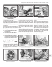
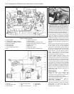
Airflow meter
8 This component measures the quantity of
air drawn into the engine, and converts this
into an electric signal which is transmitted to
the ECU.
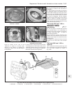
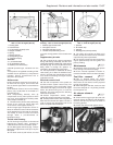
9 The intake air exerts a force on the floating
plate (1) (Fig. 13.39) which is connected to a
potentiometer (2).
10 A compensating butterfly valve (3)
compensates for any reflex pressure which
may occur, and is subject to the braking effect
of the damper chamber (4).
11 The idle mixture (air/fuel ratio) is altered by
means of the screw (8), which alters the
cross-section of the bypass channel (7).
12 An integral-type temperature sensor is
fitted, the resistance value of which decreases
as the temperature of the intake air increases.
This facility is used to correct the mixture
strength within a pre-determined air
temperature range.
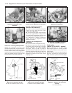
Throttle valve housing
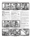
13 The housing incorporates a conventional
butterfly-type throttle valve, actuated by
cables and rods from the accelerator pedal.
14 The idle bypass channel (2) (Fig. 13.40) is
fitted with an adjustment screw (3) to vary the
idle speed.
15 The other screw (4) and locknut are used
to set the closing position of the throttle valve
plate.
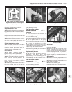
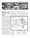
Supplementary air valve
16 This controls the air volume requirement
during cold starting. Essentially, the valve is an
electrically-heated bi-metallic strip, which rotates
the plate (4) (Fig. 13.41) to vary the volume of air
being drawn in through the aperture (1),
according to the temperature of the engine.
17 The requirement for additional air during
cold starting is to dilute the additional fuel,
which is injected and controlled by the ECU
as a result of monitoring the engine coolant
temperature sensor.
Electrical control circuit
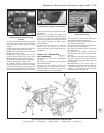
18 The main components of the system are
the ECU and the system control relay. The
relay incorporates a fuel cut-off facility, which
cuts off the fuel supply in the event of engine
failure, the vehicle turning over, or a fuel line
breaking. The relay energises the following
electrical components.
19 Coolant temperature sensor, which
signals the coolant temperature to the ECU.
20 Throttle position switch, which signals the
ECU when the throttle valve plate is closed, in
order to actuate the deceleration fuel cut-off
device at speeds above 2500 rpm.
21 The switch also signals the ECU at full
throttle, so that the mixture can be enriched to
cope with full-power requirements.
22 The system control relay also monitors the
engine speed directly from the ignition coil
primary winding.
Maintenance ¡
23 Regularly check the security of all system
hoses, wiring connections and plugs.
24 At the intervals specified in Section 3,
renew the fuel filter and the air cleaner element.
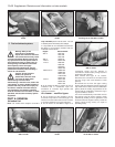
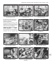
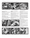
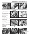
Fuel filter - renewal ¡
25 This is located within the engine
compartment just above the timing belt cover.
Disconnect the fuel hoses, but be prepared
for loss of fuel (photo).
26 When fitting the new filter, make sure that
the arrow stamped on it is pointing towards
the fuel injector rail.
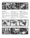
Air cleaner element -
renewal ¡
27 Prise back the toggle-type clips and take
off the air cleaner lid. Remove and discard the
element, and wipe any dirt from the inside of
the casing (photos).
28 Fit the new element and replace the lid.
Supplement: Revisions and information on later models 13•67
Fig. 13.41 Supplementary air valve -
1301 cc Turbo ie engine (Sec 9C)
1 Aperture
2 Bi-metallic strip
3 Passage
4 Rotating plate (closed position)
Fig. 13.40 Sectional view of throttle valve
housing - 1301 cc Turbo ie engine (Sec 9C)
1 Butterfly-type throttle valve
2 Idle bypass channel
3 Idle speed adjusting screw
4 Throttle valve plate setting screw
Fig. 13.39 Sectional view of airflow meter -
1301 cc Turbo ie engine (Sec 9C)
1 Floating plate
2 Potentiometer
3 Compensating butterfly valve
4 Damper chamber
6 Spring
7 Bypass channel
8 CO adjusting screw
9 Tamperproof plug
Terminals
5, 7, 8, Potentiometer
9 Air temperature sensor
E Sealed (not to be touched)
9C.27A Removing the air cleaner lid9C.25 Secondary fuel filter
13