


Cylinder head - removal and refitting
Sump pan - removal and refitting
Pistons/connecting rods - removal and
refitting
Oil pump - removal and refitting
Engine mountings - renewal
1116 cc and 1301 cc engines
Valve clearances - checking and adjusting
Camshaft and camshaft carrier - removal
and refitting
Timing belt - removal and refitting
Cylinder head - removal and refitting
Sump pan - removal and refitting
Oil pump - removal and refitting
Pistons/connecting rods - removal and
refitting
Engine mountings - renewal
Part 2:
903 cc engine
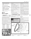
5 Valve clearances -
adjustment
2
1 Adjust the valves when the engine is cold.
2 Unbolt and remove the rocker cover.
3 It is important that the clearance is set
when the cam follower of the valve being
adjusted is on the heel of the cam (ie;
opposite the peak). This can be done by
carrying out the adjustments in the following
order, which also avoids turning the
crankshaft more than necessary.
4 Turn the crankshaft either using a spanner
on the pulley nut or by raising a front
roadwheel, engaging a gear (3rd or 4th) and
turning the wheel in the forward direction of
travel. It will be easier to turn the engine if the
spark plugs are first removed.
Valve fully open Check and adjust
Valve No. 8 EX Valve No. 1 EX
Valve No. 6 IN Valve No. 3 IN
Valve No. 4 EX Valve No. 5 EX
Valve No. 7 IN Valve No. 2 IN
Valve No. 1 EX Valve No. 8 EX
Valve No. 3 IN Valve No. 6 IN
Valve No. 5 EX Valve No. 4 EX
Valve No. 2 IN Valve No. 7 IN
5 Count the valves from the timing cover end
of the engine.
6 Remember, the inlet and exhaust valve
clearances are different.
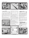
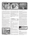
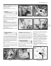
7 Insert the appropriate feeler gauge between
the end of the valve stem and the rocker arm.
It should be a stiff sliding fit (photo).
8 If the clearance is incorrect, release the
rocker arm adjuster screw locknut using a ring
spanner. Turn the adjuster screw using a
small open-ended spanner, but tie something
to it in case it is inadvertently dropped
through one of the pushrod holes.
9 Once the clearance is correct, tighten the
locknut without moving the position of the
adjuster screw.
10 Repeat the operations on the remaining
seven valves.
11 Re-check all the clearances. Make sure
that the rocker cover gasket is in good
condition and fit the rocker cover.
6 Timing chain and sprockets
- removal and refitting
3
1 Remove the alternator drivebelt as
described in Chapter 2.
2 Unscrew and remove the crankshaft pulley
nut.
3 Disconnect the hoses from the fuel pump.
4 Unbolt and remove the fuel pump with
spacer and rod.
5 Support the engine on a hoist or under the
sump and disconnect and remove the
right-hand mounting. Then unscrew and
remove the timing cover bolts. The base of
the cover is secured by the front two sump
pan studs. Unbolt and lower the front end of
the sump. Avoid breaking the gasket. Remove
the timing cover.
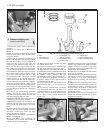
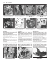
6 Undo and remove the camshaft sprocket
securing bolt; this will also release the fuel
pump drive cam from the end of the camshaft.
Note the timing marks on the camshaft and
crankshaft sprockets.
7 Using two tyre levers, carefully ease the two
sprockets forwards away from the crankcase.
Lift away the two sprockets and timing chain.
8 Remove the Woodruff key from the
crankshaft nose with a pair of pliers and note
how the channel in the pulley is designed to fit
over it. Place the Woodruff key in a container
as it is a very small part and can easily
become lost. The camshaft sprocket is
located on the camshaft by a dowel peg.
Refitting
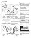
9 Fit the Woodruff key to the front of the
crankshaft.
10 Tap the crankshaft sprocket onto the front
of the crankshaft.
11 Turn the sprocket so that the Woodruff
key is uppermost.
12 Turn the camshaft until it is in such a
position that if the sprocket was fitted the
dimple timing mark on the sprocket would be
nearest to and in alignment with, the one on
the crankshaft sprocket.
903 cc engine 1•9
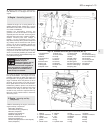
5.7 Adjusting a valve clearance
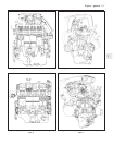
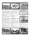
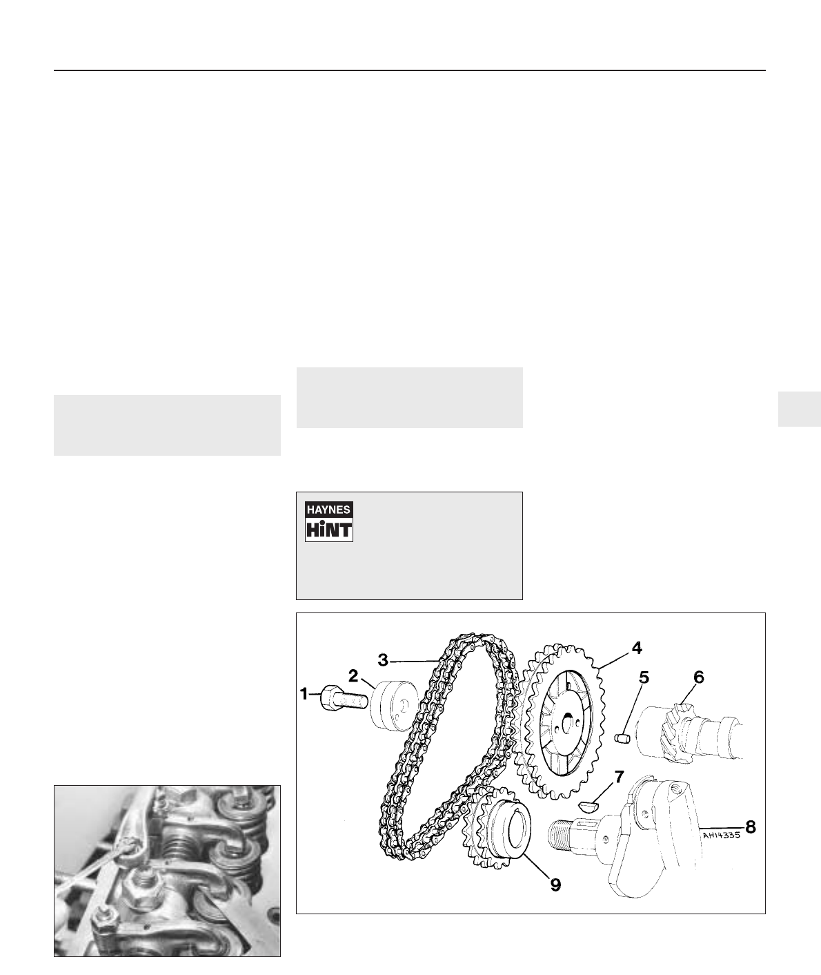
1 Sprocket retaining bolt
2 Fuel pump eccentric cam
3 Timing chain
4 Camshaft sprocket
5 Sprocket locating dowel
6 Camshaft
7 Woodruff key
8 Crankshaft
9 Crankshaft sprocket
Fig. 1.6 Timing chain and sprockets (Sec 6)
1
To prevent the crankshaft
rotating, either select a gear
and have an assistant apply
the footbrake hard or
remove the starter motor and lock the
ring gear teeth with a large cold chisel
or screwdriver.