


this type is used and the engine is in good
condition, the spark plugs should not need
attention between scheduled replacement
intervals. Spark plug cleaning is rarely
necessary and should not be attempted unless
specialised equipment is available as damage
can easily be caused to the firing ends.
2 At the specified intervals, the plugs should
be renewed. The condition of the spark plug
will also tell much about the overall condition
of the engine.
3 If the insulator nose of the spark plug is
clean and white, with no deposits, this is
indicative of a weak mixture, or too hot a plug.
(A hot plug transfers heat away from the
electrode slowly - a cold plug transfers it away
quickly.)
4 If the tip of the insulator nose is covered
with sooty black deposits, then this is
indicative that the mixture is too rich. Should
the plug be black and oily, then it is likely that
the engine is fairly worn, as well as the mixture
being too rich.
5 The spark plug gap is of considerable
importance, as, if it is too large or too small
the size of the spark and its efficiency will be
seriously impaired. The spark plug gap should
be set to the gap shown in the Specifications
for the best results.
6 To set it, measure the gap with a feeler
gauge, and then bend open, or close, the
outer plug electrode until the correct gap is
achieved. The centre electrode should never
be bent as this may crack the insulation and
cause plug failure, if nothing worse.
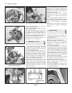
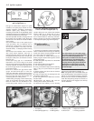
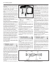
7 When fitting new plugs, check that the plug
seats in the cylinder head are quite clean.
Refit the leads from the distributor in the
correct firing order, which is 1-3-4-2; No 1
cylinder being the one nearest the flywheel
housing (903 cc) or timing belt (1116 or
1301 cc). The distributor cap is marked with
the HT lead numbers to avoid any confusion.
Simply connect the correctly numbered lead
to its respective spark plug terminal (photo).
12 Ignition switch -
removal and refitting
1
1 Access to the steering column lock/ignition
switch is obtained after removing the steering
wheel and column shrouds (Chapter 10) and
the column switch unit (Chapter 9).
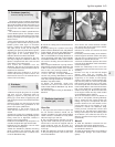
2 In the interest of safety, disconnect the
battery negative lead and the ignition switch
wiring plug (photo).
3 Insert the ignition key and turn to the STOP
position (photo).
4 Pull the two leads from the switch.
5 Turn the ignition key to MAR.
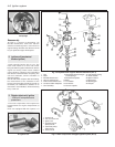
6 Using a screwdriver depress the retaining
tabs (1) (Fig. 4.16) and release the ignition
switch.
7 Set the switch cam (2) so that the notches
(3) are in alignment.
8 Insert the switch into the steering lock and
engage the retaining tabs.
9 Turn the ignition key to STOP and connect
the two leads.
10 Reconnect the battery and refit the
steering wheel, switch and shrouds.
11 Removal and refitting of the steering
column lock is described in Chapter 10.
Note: The ignition key is removable when set
to the STOP position and all electrical circuits
will be off. If the interlock button is pressed,
the key can be turned to the PARK position in
order that the parking lamps can be left on
and the steering lock engaged, but the key
can be withdrawn.
4•8 Ignition system
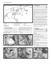
Fig. 4.16 Typical ignition switch (Sec 12)
1 Retaining tabs 3 Alignment notches
2 Switch cam 4 Locating projection
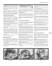
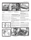
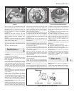
12.3 Ignition key positions
1 AVV (Start) 3 Stop (Lock)
2 Park (Parking lights on) 4 MAR (Ignition)
12.2 Ignition switch and lock
11.7 Distributor cap HT lead markings
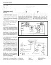
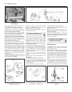
Fig. 4.15 Spark plug connections on
1116 cc and 1301 cc engines (Sec 11)
Fig. 4.14 Spark plug connections on
903 cc engine (Sec 11)
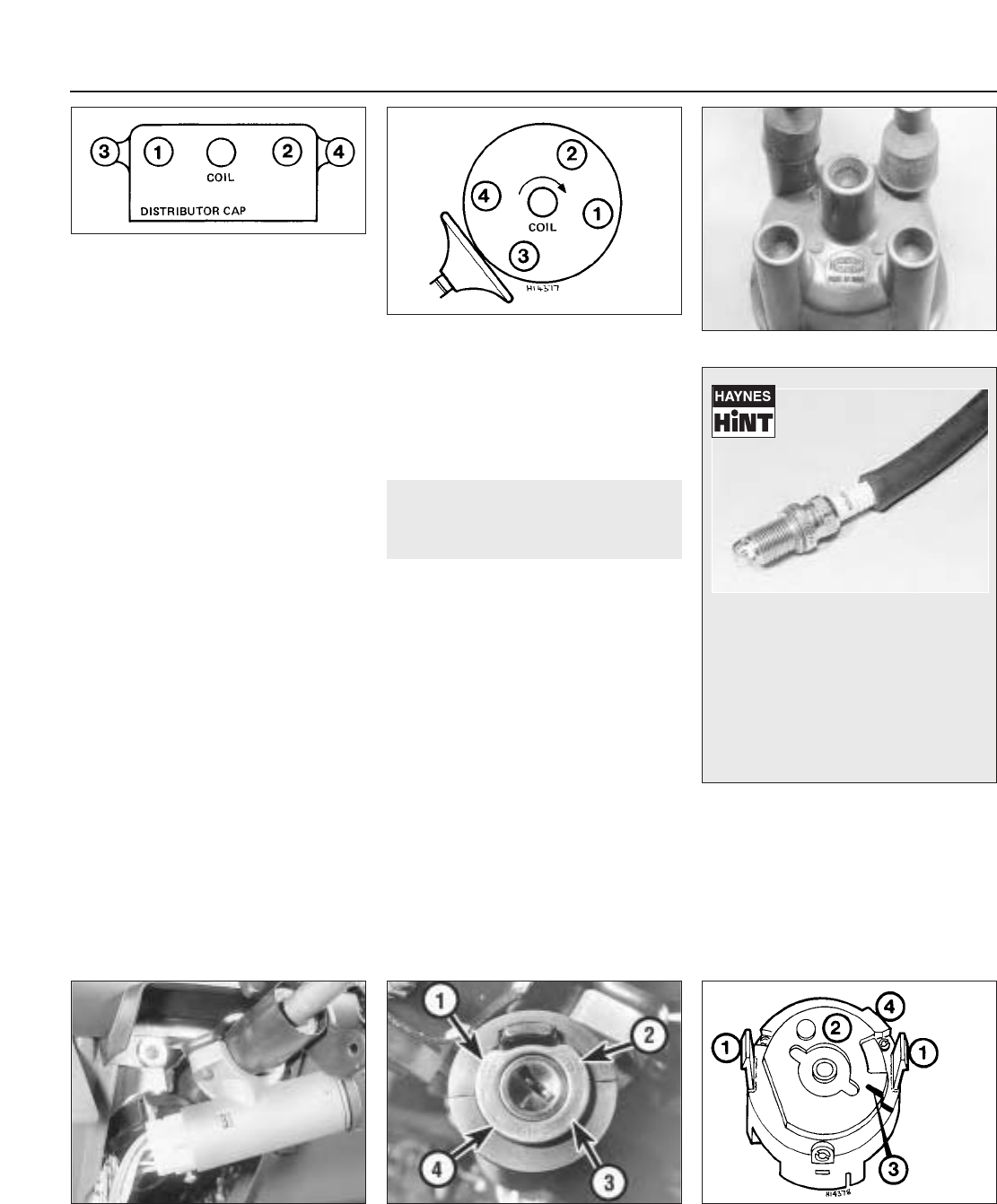
It’s often difficult to insert spark plugs
into their holes without cross-threading
them. To avoid this possibility, fit a
short piece of rubber hose over the end
of the spark plug. The flexible hose
acts as a universal joint, to help align
the plug with the plug hole. Should the
plug begin to cross-thread, the hose
will slip on the spark plug, preventing
thread damage.