


light alloy construction and is easily damaged
use a blunt scraper or rotary wire brush to
clean all traces of carbon deposits from the
combustion spaces and the ports. The valve
head stems and valve guides should also be
freed from any carbon deposits. Wash the
combustion spaces and ports down with
paraffin and scrape the cylinder head surface
free of any foreign matter with the side of a
steel rule, or a similar article.
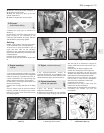
8 If the engine is installed in the car, clean the
pistons and the top of the cylinder bores. If
the pistons are still in the block, then it is
essential that great care is taken to ensure
that no carbon gets into the cylinder bores as
this could scratch the cylinder walls or cause
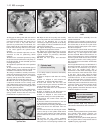
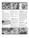
damage to the piston and rings. To ensure
this does not happen, first turn the crankshaft
so that two of the pistons are at the top of
their bores. Stuff rag into the other two bores
or seal them off with paper and masking tape.
The waterways should also be covered with
small pieces of masking tape to prevent
particles of carbon entering the cooling
system and damaging the coolant pump.
9 With a blunt scraper carefully scrape away
the carbon from the piston crown, taking care
not to scratch the aluminium. Also scrape
away the carbon from the surrounding lip of
the cylinder wall. When all carbon has been
removed, scrape away the grease which will
now be contaminated with carbon particles,
taking care not to press any into the bores. To
assist prevention of carbon build-up the
piston crown can be polished with a metal
polish. Remove the rags or masking tape from
the other two cylinders and turn the
crankshaft so that the two pistons which were
at the bottom are now at the top. Place rag in
the cylinders which have been decarbonised,
and proceed as just described.
10 Examine the head of the valves for pitting
and burning, especially the heads of the
exhaust valves. The valve seatings should be
examined at the same time. If the pitting on
the valve and seat is very slight, the marks
can be removed by grinding the seats and
valves together with coarse, and then fine,
valve grinding paste.
11 Where bad pitting has occurred to the
valve seats it will be necessary to recut them
and fit new valves. This latter job should be
entrusted to the local agent or engineering
works. In practice it is very seldom that the
seats are so badly worn. Normally it is the
valve that is too badly worn for refitting, and
the owner can easily purchase a new set of
valves and match them to the seats by valve
grinding.
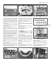
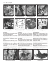
12 Valve grinding is carried out as follows.
Smear a trace of coarse carborundum paste
on the seat face and apply a suction grinder
tool to the valve head. With a semi-rotary
motion, grind the valve head to its seat, lifting
the valve occasionally to redistribute the
grinding paste. When a dull matt even surface
is produced on both the valve seat and the
valve, wipe off the paste and repeat the
process with fine carborundum paste, lifting
and turning the valve to redistribute the paste
as before. A light spring placed under the
valve head will greatly ease this operation.
When a smooth unbroken ring of light grey
matt finish is produced, on both valve and
valve seat faces, the grinding operation is
complete. Carefully clean away every trace of
grinding compound, take great care to leave
none in the ports or in the valve guides. Clean
the valve seats with a paraffin soaked rag,
then with a clean rag, and finally, if an air line
is available, blow the valves, valve guides and
valve ports clean.
13 Check that all valve springs are intact. If
any one is broken, all should be renewed.
Check the free height of the springs against
new ones. If some springs are not within
specifications, replace them all. Springs suffer
from fatigue and it is a good idea to renew
them even if they look serviceable.
14 Check that the oil supply holes in the
rocker arms are clear.
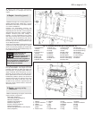
15 The cylinder head can be checked for
warping either by placing it on a piece of plate
glass or using a straight-edge and feeler
blades. If there is any doubt or if its block face
is corroded, have it re-faced by your dealer or
motor engineering works.
16 Test the valves in their guides for side to
side rock. If this is any more than almost
imperceptible, new guides must be fitted.
Again this is a job for your dealer as a special
tool is required to ensure the correct
installation depth and the cylinder head must
be warmed to 80ºC (176ºF) before fitting the
guides.
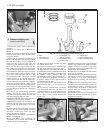
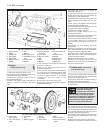
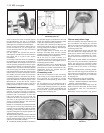
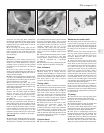
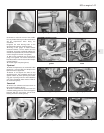
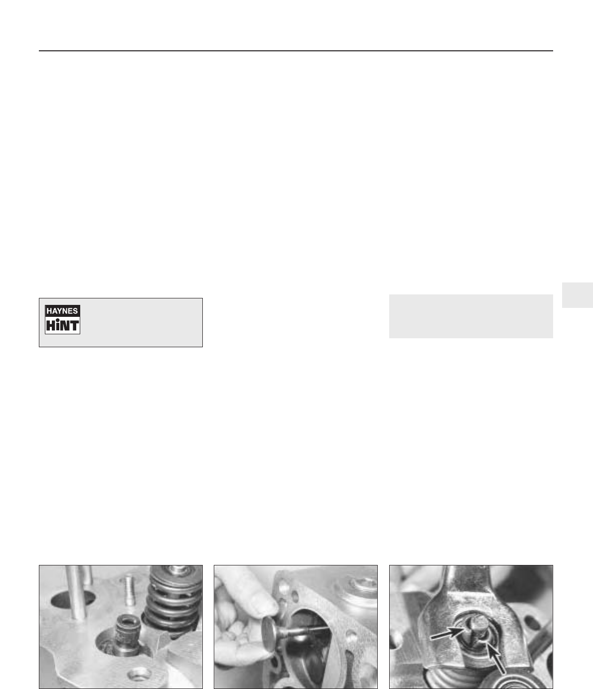
17 Commence reassembly by oiling the stem
of the first valve and pushing it into its guide
which should have been fitted with a new oil
seal (photos).
18 Fit the spring seat. Fit the valve spring so
that the closer coils are towards the cylinder
head and then fit the spring retaining cap.
19 Compress the valve spring and locate the
split cotters in the valve stem cut-out (photo).
20 Gently release the compressor, checking
to see that the collets are not displaced.
21 Fit the remaining valves in the same way.
22 Tap the end of each valve stem with a
plastic or copper-faced hammer to settle the
components.
23 The cylinder head is now ready for
refitting as described in Section 7.
18 Examination and renovation
4
1 With the engine stripped down and all parts
thoroughly clean, it is now time to examine
everything for wear. The following items
should be checked and where necessary
renewed or renovated as described in the
following Sections.
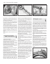
Cylinder block and crankcase
2 Examine the casting carefully for cracks
especially around the bolt holes and between
cylinders.
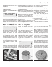
3 The cylinder bores must be checked for
taper, ovality, scoring and scratching. Start by
examining the top of the cylinder bores. If they
are at all worn, a ridge will be felt on the thrust
side. This ridge marks the limit of piston ring
travel. The owner will have a good indication
of bore wear prior to dismantling by the
quantity of oil consumed and the emission of
blue smoke from the exhaust especially when
the engine is cold.
4 An internal micrometer or dial gauge can be
903 cc engine 1•17
17.19 Fitting split collets17.17B Inserting a valve into its guide17.17A Valve stem oil seal
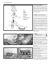
1
Press a little grease into the
gap between the cylinder
walls and the two pistons
which are to be worked on.