


98 Commence reassembly by liberally oiling
the bearings in the housing, and the oil seal lip.
99 Carefully insert the camshaft into the
housing from the blanking plate/distributor
end, taking care to avoid damage to the
bearings.
100 Refit the blanking plate using a new
gasket.
101 Refit the camshaft housing as described
previously in this Section.
Cylinder head
(1372 cc ie engine) -
removal and refitting #
Note: The following instructions describe
cylinder head removal and refitting leaving the
camshaft, manifolds and associated items in situ
In the head. If required, these items can be
removed separately. When removing the
cylinder head the engine must be cold - do not
remove the head from a hot engine. A new
cylinder head gasket and any associated gaskets
must be used during reassembly. FIAT specify
that the main cylinder head bolts should be
renewed after they have been used (ie tightened)
four times. If in any doubt as to the number of
times that they have been used renew them as a
precaution against possible failure.
Warning: Refer to the beginning
of Section 9 before starting any
work.
102 Depressurise the fuel supply system as
described in Section 9 of this Chapter.
103 Disconnect the battery negative lead.
104 Drain the engine coolant as described in
Section 8.
105 Remove the air cleaner unit as described
in Section 9.
106 Remove the timing belt as described
previously in this Section.
107 Disconnect the crankcase ventilation
hose from the cylinder head and the SPi
injector unit.
108 Disconnect the accelerator cable at the
engine end.
109 Detach the engine idle speed check
actuator lead, the inlet manifold vacuum
sensor lead, the coolant temperature sensor
lead, the injector supply lead, the throttle
position switch lead and the distributor cap
(with HT leads). Position them out of the way.
110 Disconnect the brake servo hose from
the manifold.
111 Disconnect the coolant hoses from the
thermostat and the inlet manifold.
112 Slowly release the fuel supply and return
hose retaining clips and detach the hoses
from the injector unit housing and
connections. Catch any fuel spillage in a clean
cloth and plug the hoses to prevent the
ingress of dirt and further fuel loss.
113 Unbolt and detach the exhaust downpipe
from the manifold.
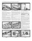
114 Loosen off the cylinder head retaining
bolts in a progressive manner, reversing the
sequence shown in Fig. 13.17. When all of the
bolts are loosened off, extract them and
collect the washers.
115 Check that all fittings and associated
attachments are clear of the cylinder head,
then carefully lift the head from the cylinder
block. If necessary tap the head lightly with a
soft-faced mallet to free it from the block, but
do not lever it free between the joint faces.
Note that the cylinder head is located on
dowels.
116 Recover the old cylinder head gasket and
discard it.
117 Clean the cylinder head and block mating
surfaces by careful scraping. Take care not to
damage the cylinder head - it is manufactured in
light alloy and is easily scored. Cover the coolant
passages and other openings to prevent dirt and
carbon from falling into them. Mop out all the oil
from the cylinder head bolt holes - if oil is left in
them, hydraulic pressure, caused when the bolts
are refitted, could cause the block to crack.
118 If required the cylinder head can be
dismantled and overhauled as described in
paragraphs 129 to 131 of this Section.
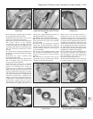
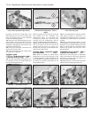
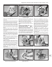
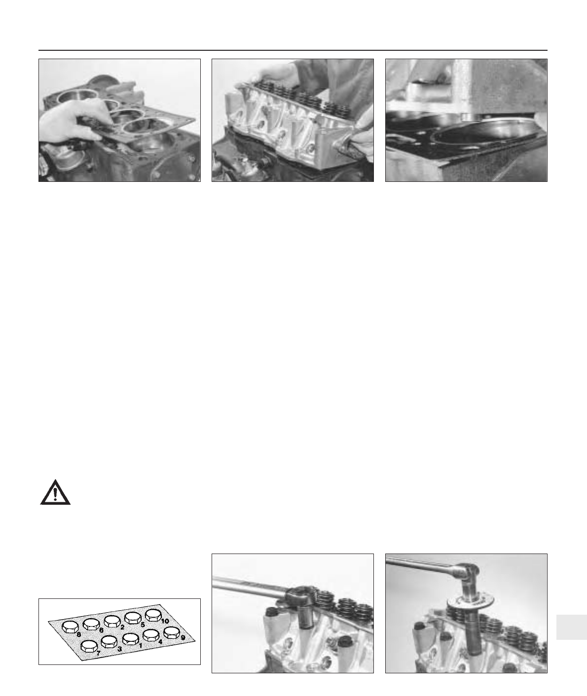
119 The new gasket must be removed from
its protective packing just before it is fitted.
Do not allow any oil or grease to come into
contact with the gasket. Commence refitting
the cylinder head by locating the new gasket
on the cylinder block so that the word “ALTO”
is facing up (photo).
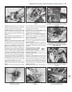
120 With the mating faces scrupulously
clean, refit the cylinder head into position and
engage it over the dowels. Refer to the note at
the beginning of this part of the Section, then
refit the ten main cylinder head bolts and
washers. Screw each bolt in as far as possible
by hand to start with. Do not fit the smaller
(M8 x 1.25) bolts at this stage (photos).
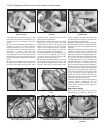
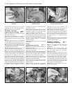
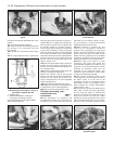
121 The bolts must now be tightened in stages
and in the sequence shown in Fig. 13.17. Refer
to the specified torque wrench settings and
tighten all bolts to the Stage 1 torque, then
using a suitable angle gauge, tighten them to
the second stage, then the third stage (photos).
122 With the main cylinder head bolts fully
Supplement: Revisions and information on later models 13•43
7B.120B . . . and engage the positioning
dowels in their holes
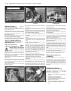
7B.120A Lower the cylinder head onto the
block . . .
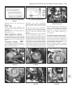
7B.119 Locating a new cylinder head
gasket on the cylinder block (engine
shown on dismantling stand)
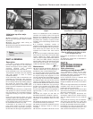
7B.121A Tighten main cylinder head bolts
to specified torque . . .
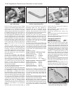
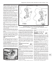
Fig. 13.17 Cylinder head bolt tightening
sequence on the 1372 cc ie and Turbo ie
engines (Sec 7B)
13
7B.121B . . . and then through the specified
angle