


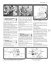

Anti-flooding device (automatic)
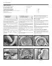
10 Pull the choke control fully out and hold the
control lever, on the anti-flooding device,
depressed. There should be a gap (Y)
(Fig. 3.27) between the edge of the choke valve
plate and the carburettor wall of between 3.75
and 4.25 mm (0.15 and 0.17 in). If adjustment is
required, turn the adjuster screw provided.
15 Carburettor
(Solex C30-32 (CIC/1) -
servicing and adjustment
4
1 The carburettor top cover with float may be
removed without the need to withdraw the
carburettor from the manifold.
2 The other adjustments described in this
Section will require removal of the carburettor.
3 Extract the top cover fixing screws and lift
away the top cover with float.
4 Refer to Section 9 paragraphs 4 and 5 for
details of removal of the fuel inlet needle
valve.
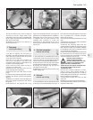
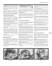
Float adjustment
5 Invert the carburettor cover so that the
weight of the floats depresses the ball of the
needle valve.
6 Measure the distance between the float and
the surface of the cover gasket. This should
be between 6.5 and 7.5 mm (0.26 and 0.30 in).
If adjustment is required, change the
thickness of the needle valve washer or
carefully bend the float arm.
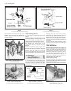
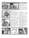
Accelerator pump
7 Refer to Section 10, paragraphs 6 and 7.
The total volume of fuel collected should be
between 7.5 and 9.5 cc. If the volume of fuel
is incorrect, release the locknut and turn the
adjuster screw on the pump lever then re-test
the volume ejected.
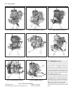
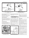
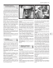
Fast idle
8 Operate the choke control lever to close the
choke valve plate. The gap between the edge
of the primary throttle valve plate and the
venturi wall should be between 0.90 and
1.00 mm (0.035 and 0.039 in). If adjustment is
required, turn the nut on the fast idle rod.
Automatic anti-flooding device
9 The vacuum system of the device can be
checked for leaks by applying a vacuum to
the drilling in the carburettor throttle valve
block. If vacuum cannot be maintained, renew
the diaphragm.
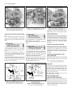
Choke valve plate automatic
opening
10 Move the choke control lever to fully close
the choke valve plate and then press the lean
out valve rod. There should now be a gap (X)
(Fig. 3.32) between the edge of the choke
valve plate and the wall of the carburettor
throat of between 4.75 and 5.25 mm (0.187
and 0.207 in).
11 Where adjustment is required, release the
locknut and turn the screw on the lean out
valve.
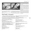
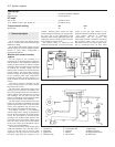
16 Economy meter
1 This device is fitted to ES (energy saving)
models. It is essentially a vacuum gauge to
advise the driver with regard to economical
throttle opening related to engine and road
speed. The point of change to a higher gear
can also be deduced from this gauge. The
latter facility is provided by an LED (light
emitting diode).
2 Fault testing of the system is described in
Chapter 9.
Fuel system 3•11
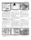
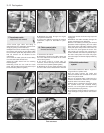
Fig. 3.29 Adjusting accelerator pump
stroke (Solex C30-32 CIC/1) (Sec 15)
Fig. 3.28 Float setting diagram
(Solex C30-32 CIC/1) (Sec 14)
A = 6.7 to 7.5 mm (0.26 to 0.30 in)
Fig. 3.32 Choke valve plate setting
(Solex C30-32 CIC/1) (Sec 15)
X = 4.75 to 5.25 mm (0.187 to 0.207 in)
Fig. 3.30 Fast idle screw on
Solex C30-32 CIC/1 (Sec 15)
A Choke control lever C Lean out valve
B Fast idle adjustment
Fig. 3.31 Vacuum drilling for automatic
anti-flooding device (Solex C30-32 CIC/1)
(Sec 15)
3
Fig. 3.27 Anti-flooding device (automatic)
adjustment diagram
(Weber 30/32 DMTR 90/250) (Sec 14)
Y = 3.75 to 4.25 mm (0.148 to 0.167 in)