


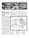
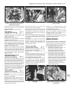
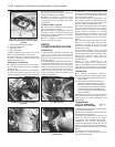
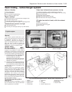

33 Detach the vacuum pick-up pipes from
the points indicated in Fig. 13.57.
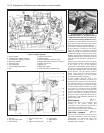
34 Detach the wiring connector from the
throttle position switch.
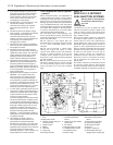
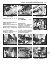
35 Unscrew and remove the inlet manifold
mounting bracket-to-cylinder head retaining
bolt shown in Fig. 13.58.
36 Unscrew and remove the injector cable
shield retaining screws. Detach the cables
from the injectors.
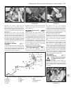
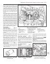
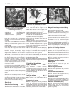
37 Disconnect the earth leads and the air
intake sensor lead shown in Fig. 13.59.
38 Release and withdraw the injector cable
shield from the left-hand underside of the
throttle housing.
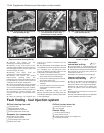
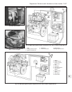
39 Unscrew and detach the injector fuel
supply pipe and disconnect the fuel pressure
regulator pipe from its inlet manifold union.
40 Disconnect the injector cooling fan
thermostatic switch lead.
41 Unscrew the securing bolts and remove
the fuel pressure regulator.
42 Unscrew and remove the heat
shield-to-exhaust manifold retaining bolts.
Unscrew the retaining bolts at the rear and
withdraw the heat shield.
43 Undo the inlet manifold retaining
bolts/nuts and carefully withdraw the
manifold/throttle housing. Remove the gasket
from the mating face.
Injectors and fuel rail
44 Depressurise the system as described
previously.
45 Disconnect the fuel supply line from the
fuel rail.
46 Disconnect the fuel return line from the
base of the fuel pressure regulator. Unbolt
and remove the pressure regulator from the
fuel rail.
47 Unscrew and remove the injector cable
shield retaining screws. Detach the cables
from the injectors.
48 Disconnect the fuel rail/injector unit and
withdraw the fuel rail, together with the
injectors, from the engine.
49 With the injectors and the fuel rail
removed, one or more injectors can be
removed and renewed as described below.
Note that the connecting hoses will be
destroyed during removal and these together
with the injector seals will therefore need to be
renewed.
Injector(s) and connecting hoses
50 Remove the injectors and the injector fuel
rail as described in the previous sub-Section
and secure the fuel rail in a vice, but do not
overtighten.
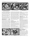
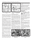
51 Cut free the hose between the fuel rail and
the injector. Make the cut in-line with the hose
and cut the hose as close as possible to the
fuel rail connection, then pull the hose free
from its retaining cap. Once the hose is
detached, the retaining cap is released.
52 Repeat the procedure and release the
hose and its retaining cap from the injector.
53 Whether or not the injector unit itself is to
be renewed, the injector O-ring seals must
always be renewed when disturbed.
54 Check that the connections of the fuel rail
and the injector are clean, then push the new
injector with retaining cap onto the new hose.
Ensure that the hose is fully located in the
retaining cap.
55 Check that the fuel rail-to-hose retaining
cap is located on the connector, then push
the other end of the injector hose over the fuel
rail connector. Ensure that the hose is fully
located in the retaining cap.
56 The interconnecting hose between the
fuel rail sections can be removed and
renewed in the same manner as that
described above for the injector hoses.
Electronic control unit (ECU)
57 The ECU is mounted on the top face of
the airflow meter. Ensure that the ignition is
switched off before disconnecting the
multiplug from the ECU. Disconnect the wiring
multiplug connector by compressing the tag
and pulling the connector free from the unit.
Undo the retaining screws and remove the
ECU from the airflow meter. Handle the unit
with care and if removed for an extensive
period, store it in a safe place where it will not
get knocked or damaged.
Fuel pump - removal and refitting
58 Depressurise the fuel system as
described previously.
59 Raise the car at the rear and support it on
axle stands. Detach and remove the
Supplement: Revisions and information on later models 13•81
Fig. 13.59 Disconnecting the earth leads
(arrowed) on the 1372 cc Turbo ie engine
(Sec 9E)
Fig. 13.58 removing the inlet manifold
mounting bracket from the cylinder head
on the 1372 cc Turbo ie engine (Sec 9E)
Fig. 13.57 Detach the vacuum pick-up
pipes from the points arrowed on the
1372 cc Turbo ie engine (Sec 9E)
Fig. 13.62 ECU (1) wiring multiplug (2) and
tag (3) - 1372 cc Turbo ie engine (Sec 9E)
Fig. 13.61 Cutting free the hose from an
injector on the 1372 cc Turbo ie engine
(Sec 9E)
Fig. 13.60 Disconnecting the injector fuel
supply pipe and fuel pressure regulator pipe
on the 1372 cc Turbo ie engine (Sec 9E)
13
2
3
3
1