


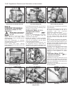
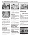
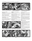
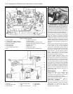

Fuel pressure regulator
60 Disconnect the vacuum hose from the
regulator (photo).
61 Anticipate some loss of pressurised fuel,
and then disconnect the fuel hose from the
regulator. Unbolt and remove the unit.
Excessive air pressure switch
62 This is screwed into the end of the inlet
manifold. Disconnect the electrical leads and
unscrew the switch.
Coolant temperature sensor
63 This is screwed into the cylinder head and
has wires connected to it. Drain the cooling
system before commencing operations.
64 Disconnect the wiring plug and unscrew
the sensor.
Throttle valve housing and inlet
manifold
65 Disconnect the air inlet hose from the
throttle valve housing, and also the
supplementary air valve hose.
66 Disconnect the throttle control cable by
swivelling the grooved sector and slipping the
cable nipple from its recess.
67 Disconnect the wiring plug from the
throttle position (potentiometer) switch.
68 Unbolt the fuel pressure regulator/wiring
loom bracket, and also the wiring loom
bracket at the other end of the inlet manifold.
Move the wiring loom aside.
69 Unbolt and remove the throttle housing
support bracket.
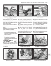
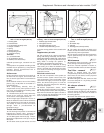
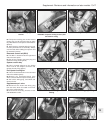
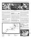
70 Disconnect the vacuum servo hose and
the fuel pressure regulator vacuum hoses
from the inlet manifold (photos).
71 Disconnect the leads from the excessive
air pressure switch.
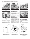
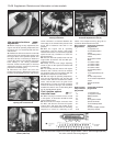
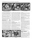
72 Unscrew the inlet manifold fixing nuts.
Note that double nuts are used at the ends of
the manifold in order to secure the exhaust
heat shield (photo). The shield should be
released and lowered to rest on the exhaust
manifold.
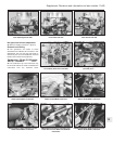
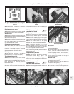
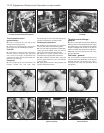
73 Unscrew and remove the remaining two
nuts now exposed by lowering the heat shield
and lifting the inlet manifold away (photo).
74 If necessary, the injectors and cooling
tube can be withdrawn, and the two twin inlet
pipe stubs removed. These are retained with
the exhaust manifolds using nuts and washers
(photo).
Fuel rail and injectors
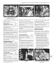
75 Disconnect the fuel delivery hose from the
fuel rail by unscrewing the union nut (photo).
Be prepared for some loss of pressurised fuel.
76 Disconnect the fuel return hose.
77 Unbolt the fuel pressure regulator and the
wiring loom brackets (photo).
78 Disconnect the air intake hose from the
throttle valve housing, and then unbolt and
remove the throttle valve housing support
bracket (photo).
79 Disconnect the hose from the injector
cooling fan, and also disconnect the fan
thermo-switch on the underside of the injector
cooling air duct (photo). Disconnect the
injector wiring plugs, and then slide out the
injector cooling air duct.
13•70 Supplement: Revisions and information on later models
9C.77 Wiring loom clip and bracket9C.75 Disconnecting the fuel delivery hose
union
9C.74 Removing an inlet manifold twin
pipe stub
9C.73 Removing the inlet manifold9C.72 Double nuts at the end of the inlet
manifold
9C.70B Fuel pressure regulator vacuum
hose connection at the inlet manifold
9C.70A Brake servo vacuum hose
connection to inlet manifold
9C.60 Fuel pressure regulator