


pump jet and give ten full strokes of the
throttle lever, pausing between each stroke to
allow fuel to finish dripping.
8 The total volume of fuel collected should be
between 2.5 and 4.5 cc. Adjust the nut on the
pump control and if necessary to increase or
decrease the volume of fuel ejected.
Fast idle adjustment
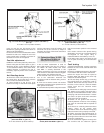
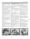
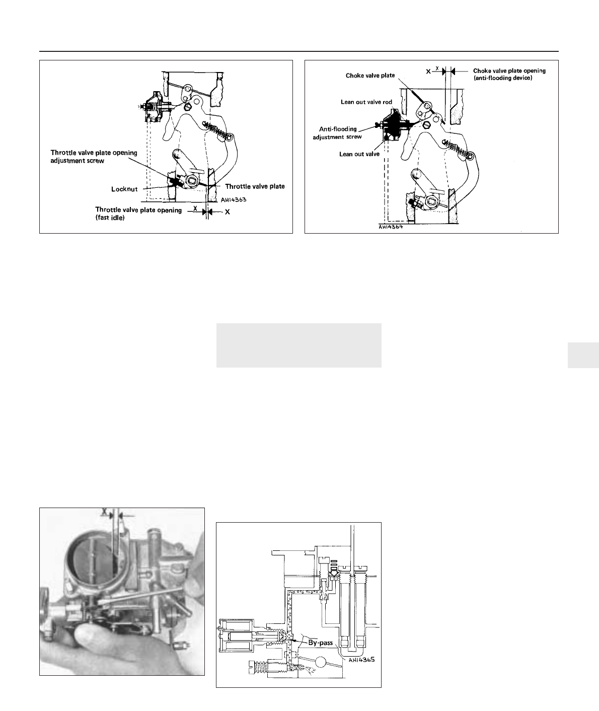
9 With the choke valve plate fully closed, the
throttle valve plate should be open to give a
dimension (X) (Fig. 3.18) of between 0.90 and
1.0 mm (0.035 to 0.039 in). Use a twist drill of
suitable diameter to measure the gap. If
necessary, adjust by means of the screw and
locknut.
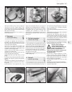
Anti-flooding device
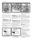
10 Close the choke valve plate by means of
the control lever. At the same time, push the
lean out valve rod towards the valve.
11 There should be a gap (X) (Fig. 3.19)
between the edge of the choke valve plate
and the carburettor throat of between 4.75
and 5.25 mm (0.187 to 0.207 in). Adjust if
necessary by means of the screw and locknut
on the lean out valve.
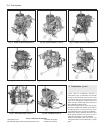
11 Carburettors (Weber 32 ICEE/
250 and Solex C32 DISA 14) -
description and adjustment
4
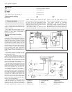
1 One of these carburettors is used on
903 cc ES engines. They are very similar to
the Weber 32 ICEV 50/250 and Solex
C32 DISA 11 already described in this
Chapter except that a fuel cut-out solenoid
valve is fitted in association with the Digiplex
ignition system (see Chapters 4 and 9).
2 The solenoid valve cuts off the supply of
fuel to the carburettor whenever the
accelerator pedal is released during overrun
conditions.
3 A fuel cut-out device control unit receives
information regarding engine speed from the
static ignition control unit.
4 A throttle butterfly switch relays information
that the accelerator pedal is in the released
state.
5 At certain minimum idle speeds during
deceleration, the fuel cut-out solenoid valve is
re-energised so that engine idling is
maintained without the tendency to cut out.
6 The Solex type control unit varies the fuel
cut-out point according to the deceleration
value.
Fault testing
7 Should a fault develop, connect a test lamp
between the fuel cut-out solenoid switch and
a good earth.
8 Connect a reliable tachometer to the engine
in accordance with the maker’s instructions.
9 Start the engine and raise its speed to
between 3000 and 4000 rev/min, then fully
release the accelerator pedal.
10 The test lamp should only go out during
the period when the accelerator pedal is
released. Should the test lamp remain on all
the time, or never come on, check the throttle
switch earth and the solenoid switch
connections.
11 Disconnect the multi-plug from the control
unit. Switch on the ignition and check that a
test lamp connected between contact 7 of the
multi-plug and earth will illuminate. If it does
not, there is an open circuit from connection
15/54 of the fuel cut-off switch.
12 Switch off the ignition and check for
continuity between contact 3 of the multiplug
and earth. An ohmmeter will be required for
this test.
13 If there is no continuity (ohmmeter shows
infinity), check all the system earth
connections. Also check that the wiring plug
under the control unit is properly connected.
14 Finally, check the engine speed signal. To
do this, a tachometer must be connected to
the single socket under the control unit within
the engine compartment.
15 If the tachometer registers correctly then
this confirms that the electronic ignition
Fuel system 3•9
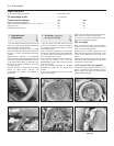
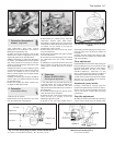
Fig. 3.18 Fast idle adjustment diagram (Solex C32 DISA 11)
(Sec 10)
X = 0.90 to 1.0 mm (0.035 to 0.039 in)
Fig. 3.19 Anti-flooding device adjustment diagram
(Solex C32 DISA 11) (Sec 10)
X = 4.75 to 5.25 mm (0.187 to 0.207 in)
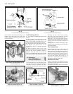
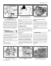
Fig. 3.21 Sectional view of fuel cut-off
switch (Solex C32 DISA 14) (Sec 11)
Fig. 3.20 Moving lean out valve rod
(Solex C32 DISA 11) (Sec 10)
X = 4.75 to 5.25 mm (0.187 to 0.207 in)
3