


Wiring diagrams 14•21
14
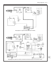
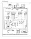
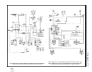
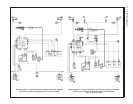
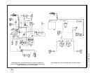
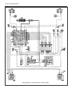
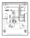
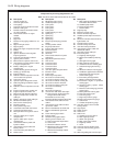
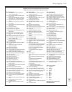
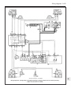
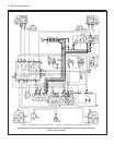
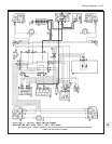
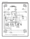
Component key for wiring diagrams 30 to 52 (continued)
Note: Not all the items listed will be fitted to all models
No Description
111 Push button on left front pillar for
centre courtesy light
112 Front electric windows switch panel,
driver’s side
113 Join between dashboard cable and
adjustable map reading light cables
114 Join with left front electric window
cables
115 Join between dashboard cable and
rear cables
116 Join between rear cable and courtesy
light cables
117 Left front speaker
118 Handbrake ‘on’ switch
119 Centre courtesy light bulb
119AAdjustable map reading light on rear
view mirror
120 Right front electric window motor
121 Right front central locking geared
motor
122 Switch signalling right front door ajar
123 Push button on right front pillar for
centre courtesy light
124 Electric windows control panel,
passenger side
125 Fuel level gauge
126 Join with right front electric window
cables
127 Join between engine cable and
dashboard cables
128 Right front speaker
129 Left rear light cluster
130 Join between rear cable and luggage
compartment courtesy light
131 Windscreen washer pump wiring join
132 Rear screen washer pump wiring join
133 Left rear earth
134 Rear screen wiper motor
135 Electric fuel pump
136 Rear number plate lamp
137 Heated rear screen
138 Right rear light cluster
139 Rear foglamp go-ahead switch
140 Join between front cable and antiskid
brakes cables
141 Join between front cable and antiskid
brakes cables
142 25 A fuse for antiskid brakes
143 Antiskid braking system control unit
144 Left modulator for antiskid brakes
145 Right modulator for antiskid brakes
146 Sensor on left front wheel
147 Sensor on right front wheel
148 10A fuse for antiskid braking system
149 Vacuum switch for antiskid braking
system
150 Antiskid braking system engagement
relay
151 Antiskid braking system failure
signalling switch
152 Digiplex electronic ignition control
unit
No Description
153 Bosch SPi Mono-Jetronic injection
system control unit
155 Join between engine cable and
injection cables
156 Join between engine cable and rear
cables for SPi system
157 Idle adjustment actuator
158 Throttle position switch
159 Injector current restriction resistor
(SPi)
162 Engine cut-out solenoid
163 Idle cut-out solenoid valve
168 Tachometer electro-magnetic sensor
169 Automatic heater control unit
170 Heater fan
171 Outside temperature sensor
172 Mixed air temperature sensor
173 Air mixture flap electrical control
motor
174 Diagnostic socket for automatic
heater
175 Connector block
176 Connector block
177 Join with cables for automatic heater
178 Radiator coolant circulation solenoid
valve
179 Automatic heater unit:
A Temperature control potentiometer
B Fan speed control potentiometer
C Heater controls light bulbs
D Ideogram signalling automatic
function engaged
E Automatic function engaged
switch
180 Horn
181 Check Panel:
A Insufficient engine oil level warning
light
B Insufficient coolant level warning
light
C Failure with side lights/rear
foglamp/rear number
plate light/braking lights warning light
D Insufficient brake fluid level
warning light
E Door ajar warning light
F Brake pad wear warning light
182 Earth on dashboard
183 Join with cables for central locking
184 Join with cables for central locking
185 Left rear central locking geared motor
186 Right rear central locking geared
motor
187 Contact on choke lever
188 Resistor for inlet manifold heating
189 Pre-heating thermal switch
191 Heated Lambda sensor
192 Lambda sensor protective fuse
193 Silicon diode
194 Join between front cable and injection
cable
197 Connector block
No Description
198 Rear cable join
199 Insufficient engine oil level sensor
200 Insufficient coolant level sensor
201 Switch signalling left rear door ajar
202 Switch signalling right rear door ajar
203 Switch on gear selector
204 Light for gear selector panel signalling
gear engaged
205 Parking signal not on
206 Connector block
207 Join in engine compartment with
injection cables
208 Petrol vapour cut out-solenoid valve
209 Petrol vapour cut out-solenoid valve
210 Airflow meter
211 Speedometer relay
212 LE2 Jetronic electronic injection
control unit
213 Connector block
214 Connector block
215 Connector block
216 Ignition cable join
217 Join between front cable and
emission control cable
218 Join between front cable and battery
cable
219 Injection system air temperature
sensor
220 Ignition control unit relay feed
225 Front cable join
226 Front cable join
227 Dim-dip circuit cut out switch
228 Dim-dip circuit resistance
229 Dim-dip circuit 7.5 A protective fuse
230 Driver’s side seat heated pad
231 Driver’s seat backrest heated pad
232 10 A protective fuse for driver’s seat
heated pads
233 Foglamps go-ahead switch
234 Driving lights cut out switch
235 Dipped headlamps relay
236 Main beam headlamps relay
237 Join between engine cable and
dashboard cables
Wire colour codes
A Light blue
B White
C Orange
G Yellow
H Grey
L Blue
M Brown
N Black
R Red
S Pink
V Green
Z Violet
Example of two-colour wire:
BN (White/Black)