


operation twice. Also prior to making
adjustments ensure that the supplementary
air valve pipe is in good condition, with no
leaks. Compress the air valve pipe using a
pair of grips to prevent incorrect adjustment
caused by a defective supplementary air
valve.
15 The air cleaner must be connected when
checking and/or adjusting the engine idle
speed. To adjust, turn the adjuster screw in
the required direction to set the engine idle
speed to that specified.
16 It is unlikely that the mixture will require
adjustment and unless this is proven by
measuring the exhaust gases using a CO
content analyser, its setting should not be
altered. As with idle speed adjustment, the
engine must be at its normal operating
temperature when making this check and
adjustment. It is also necessary to ensure that
the ignition idle advance is as specified.
Checking and adjustment must not be made
with the engine cooling fan, air conditioning
(where fitted) or other related items switched
on.
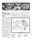
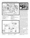
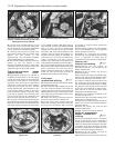
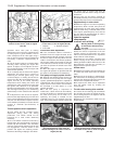
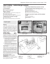
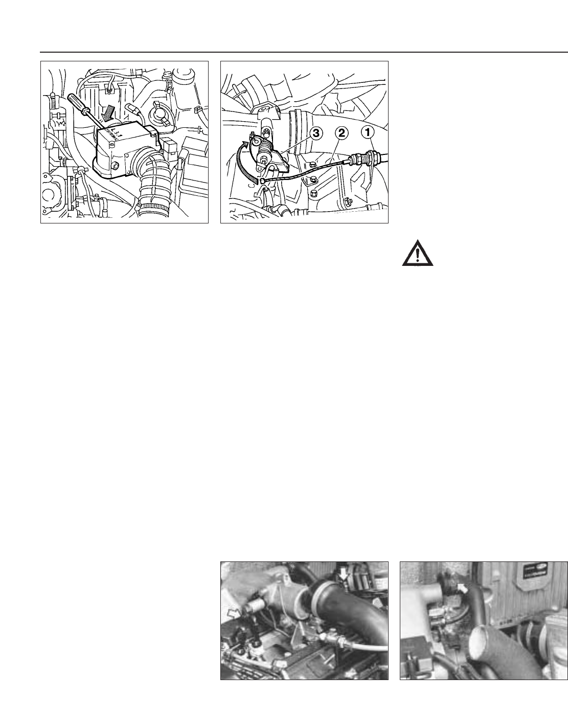
17 If adjustment to the mixture is required,
prise free the tamperproof plug from the front
of the mixture adjustment screw in the control
unit, then turn the screw as required. Turn the
screw inwards (clockwise) to increase the CO
content or outwards (anti-clockwise) to
weaken it.
Throttle position switch adjustment
18 This switch will not normally require
adjustment having been set during
production. The switch should not be
loosened off or reset unless absolutely
necessary.
19 If a new switch is fitted it can be set by
loosely fitting the securing bolts, turning the
switch fully anti-clockwise, then clockwise
until one of the internal contacts is felt to click
into engagement. Hold the switch in this
position and tighten the retaining screws.
Reconnect the wiring multiplug to the switch.
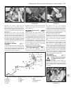
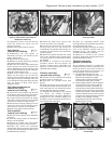
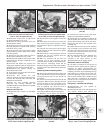
Accelerator cable adjustment
20 If the accelerator cable is removed or
detached from the support bracket at the
throttle control housing at any time, care must
be taken to adjust it correctly. When the inner
cable is connected to the throttle quadrant,
set the outer cable in the bracket so that the
inner cable has a minimal amount of free play,
yet does not prevent the throttle valve from
fully closing.
21 When the engine is restarted, check that
the engine idle speed is as specified and that
the action of the accelerator is satisfactory.
Fuel pump and supply system checks
22 Although the following basic checks can
be made to the fuel pump and fuel supply
system, specialised equipment is required to
undertake full and accurate tests of the fuel
supply system. Such checks must therefore
be entrusted to a FIAT dealer or a fuel
injection specialist.
23 If the fuel pump is suspected of
malfunction, a basic check can be made by
turning the ignition on and listening around
the area of the pump unit to hear if it is
operating. The pump is located on the
underside of the car, just forward of the fuel
tank. If the pump fails to operate, check that
the pump fuse is sound and that its
connection (and also that the relay) are clean
and secure.
24 The pump can be further checked as
described previously for the LE2 fuel injection
system fuel pump in Part C of this Section.
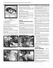
Supplementary air valve check
25 With the engine at its normal operating
temperature, allow it to idle, then pinch the
supplementary air valve hose using suitable
pliers as shown in Fig. 13.52 and check to see
if the engine speed drops by more than 50
rpm. If it does, the supplementary air valve is
defective and in need of renewal.
Injection system
components -
removal and refitting ¡
Warning: Refer to the beginning
of this Section before starting
any work.
26 With the exception of the items mentioned
below, the various components of the fuel
injection system are removed in the same
manner as that described for the equivalent
items in Part C of this Chapter.
27 Disconnect the battery negative lead
before carrying out any of the removal and
refitting operations. Where fuel lines are to be
disconnected it will first be necessary to
depressurise the injection system.
Airflow meter
28 Release the retaining clips and detach the
air intake and outlet ducts from the airflow
meter.
29 Ensure that the ignition is switched off,
then disconnect the multiplug from the ECU.
Unscrew the retaining bolts and remove the
airflow meter complete with the ECU.
30 If required, the ECU can be separated
from the airflow meter by undoing the
securing bolts.
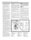
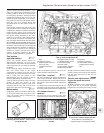
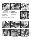
Throttle valve housing/inlet manifold
31 Loosen off the retaining clip and detach
the air intake duct from the throttle housing,
the air cooling hoses for the injectors and the
supplementary air valve.
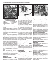
32 Detach the accelerator cable from the
throttle linkage.
13•80 Supplement: Revisions and information on later models
Fig. 13.56 Disconnecting the injector air
cooling hoses and the supplementary air
valve hose on the 1372 cc Turbo ie engine
(Sec 9E)
Fig. 13.55 Disconnecting the air intake
duct and accelerator cable from the
throttle housing on the 1372 cc Turbo ie
engine (Sec 9E)
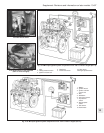
Fig. 13.54 Accelerator cable adjustment
on the 1372 cc Turbo ie engine (Sec 9E)
1 Adjuster 3 Quadrant support
2 Inner cable
Fig. 13.53 Mixture adjustment screw
location on the 1372 cc Turbo ie engine
(Sec 9E)