


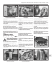
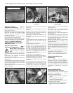
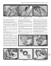

the crankcase to operate the oil pressure
gauge. In addition, a low oil pressure switch
screwed into the camshaft oil gallery actuates
a warning light on the instrument panel in the
event of the pressure dropping dangerously
low (photo).
10 Oil supply/return ducts provide the
turbocharger lubrication.
PART B:
OPERATIONS POSSlBLE
WITH ENGINE IN CAR
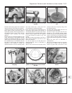
Camshaft and camshaft
carrier - removal and
refitting #
Warning: Refer to the beginning
of Section 9 before starting any
work.
1 Disconnect the battery, negative lead first.
2 Disconnect its leads and unbolt the
distributor from the end of the camshaft, and
place it to one side.
3 Disconnect the air intake hose from the
throttle valve housing.
4 Disconnect the short throttle control cable
from its sector.
5 Remove the throttle cable support bracket.
6 Disconnect the earth leads from the
camshaft cover.
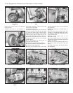
7 Refer to Section 9, Part C of this
Supplement and remove the following
components.
Supplementary air valve
Inlet manifold with fuel pressure regulator
and excess pressure safety switch
Injector cooling duct
8 Disconnect the wiring plug from the
Microplex ignition anti-knock sensor.
9 Carry out the operations described in
Chapter 1, Section 27, paragraphs 4 to 12.
10 Refitting is a reversal of removal, referring
to Section 28 of Chapter 1 for the timing belt
refitting procedure, and to Chapter 1, Sec-
tion 27, paragraphs 15 to 18.
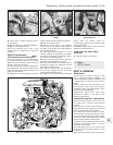
Cylinder head -
removal and refitting #
11 Carry out the operations described in
paragraphs 4 to 9 in the preceding
sub-Section, then refer to Chapter 1, Section
29, but ignore all references to the
carburettor.
12 Note the distributor mounting cover.
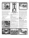
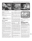
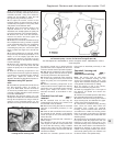
13 Four additional cylinder head bolts are
used on these engines, adjacent to the spark
plugs (photo). Note that their tightening torque
differs from the other cylinder head bolts - see
Specifications. These four bolts are tightened
13•34 Supplement: Revisions and information on later models
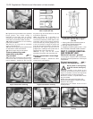
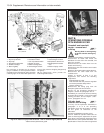
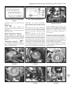
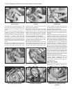
1 Oil pick-up strainer
2 Oil pump
3 Oil pressure relief valve
4 Oil filter cartridge
5 Main oil gallery
6 Camshaft oil feed
7 Low oil pressure switch
8 Engine oil cooler
9 Filter mounting base
10 Turbocharger oil feed
11 Turbocharger oil return
12 Oil pressure sender unit
13 Oil temperature sender
unit
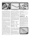
14 Piston oil spray nozzle
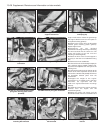
Fig. 13.12 Piston oil spray nozzle locations - 1301 cc Turbo ie engine (Sec 6A)
Letters denote cylinder bore grade
Fig. 13.11 1301 cc Turbo ie engine lubrication system (Sec 6A)
6A.9 Oil pressure sender unit