


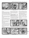
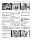
173 Lift the intermediate plate from the oil
pump body.
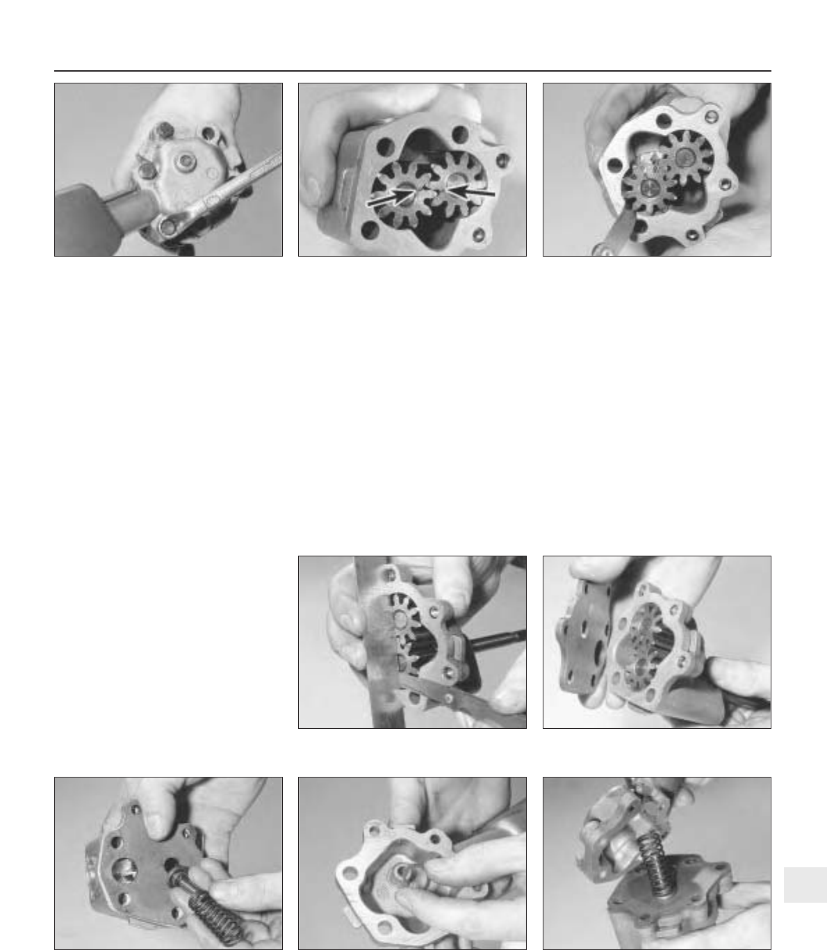
174 The gears can now be removed from the
oil pump body. Inspect them for obvious signs
of wear or damage, and renew if necessary.
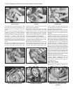
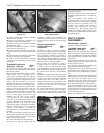
175 Commence reassembly by lubricating
the gears with clean engine oil, and refitting
them to the casing. Note that the scribed
marks on the top faces of the gears should
face each other with the gears installed
(photo).
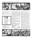
176 Using a feeler gauge, check that the
clearance between the gears and the pump
body is within the limits given in the Specifica-
tions (photo).
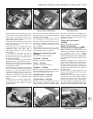
177 Using a straight-edge placed across the
top of the pump body and the gears, and a
feeler gauge, check that the gear endfloat is
within the limits given in the Specifications
(photo).
178 If either the gear-to-body clearance, or
the gear endfloat is outside the specified
limits, both gears should be renewed.
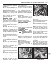
179 Locate the intermediate plate on the
pump body (photo).
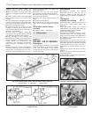
180 Place the pressure relief valve and spring
over the pressure relief hole in the
intermediate plate, and locate the spring seat
over the boss in the pump cover, then refit the
pump cover, ensuring that the pressure relief
valve components seat correctly (photos).
181 Refit and tighten the pump cover
securing bolts.
182 Thoroughly clean the mating faces of the
pump and crankcase before refitting the
pump. Prime the pump by injecting clean
engine oil into it and turning it by hand.
183 Fit the pump using a new gasket, then
insert the securing bolts and tighten them.
184 Refit the sump and top up the engine oil
level.
Pistons/connecting rods -
removal and refitting #
185 Remove the sump and the cylinder head
as described previously in this Section.
186 The big-end caps and connecting rods
normally have identification marks stamped
into their sides, facing the coolant pump side
of the cylinder block. If no marks are present,
use a centre-punch to identify the bearing
caps and the connecting rods for location.
187 Turn the crankshaft so that No. 1
crankpin is at its lowest point, then unscrew
the nuts and tap off the bearing cap. Keep the
bearing shells in the cap and the connecting
rod if they are to be re-used, taping them in
position if necessary to avoid loss.
188 Using the handle of a hammer, push the
piston and connecting rod up the bore and
withdraw it from the top of the cylinder block.
Loosely refit the cap to the connecting rod.
189 Repeat the procedure given in
paragraphs 187 and 188 on No. 4 piston and
connecting rod, then turn the crank-
shaft through half a turn and repeat the
procedure on Nos 2 and 3 pistons and
connecting rods.
190 The pistons and connecting rods and the
big-end bearings can be examined and if
Supplement: Revisions and information on later models 13•47
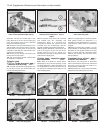
7B.176 Check gear-to-body clearance7B.175 Correct alignment of scribed marks
(arrowed) on gears
7B.171 Undo the oil pump cover bolts
7B.180C . . . then fit the cover7B.180B Locate spring seat over boss
within pump cover . . .
7B.179 Refitting the intermediate plate7B.177 Checking the gear endfloat
7B.180A Locate pressure relief valve and
spring on the intermediate plate
13