


Auxiliary control panel
(later models) -
removal and refitting ¡
61 Disconnect the battery negative lead.
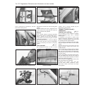
62 Insert the flat of a screwdriver under the
trim piece at the end of the auxiliary panel as
shown and prise it free. Repeat the procedure
and remove the trim piece at the other end of
the panel (photo).
63 Undo the retaining screws, withdraw the
panel from the facia. Disconnect the wiring
connectors from the panel switches to
remove the panel completely (photo).
64 A switch bulb can be renewed by
untwisting the holder and removing the holder
and bulb.
65 A switch unit can be removed from the
panel by unscrewing the four retaining screws.
66 Refitting is a reversal of the removal
procedure. Ensure that the wiring connections
are securely made and check for satisfactory
operation of the switches on completion.
Heater control panel
(later models) -
removal and refitting ¡
67 Disconnect the battery negative lead.
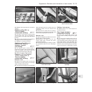
68 Pull free the heater/fresh air and blower
control knobs (photo).
69 Undo the two retaining screws and
withdraw the control panel from the facia
(photos). Detach the wiring connectors from the
panel illumination lights and remove the panel.
70 Refitting is a reversal of the removal
procedure. Ensure that the wiring connections
are securely made and on completion check
that the operation of the controls is satisfactory.
Trip master ¡
71 This electronic instrument is fitted into the
check panel of 1100SL and 1300SL models
from 1986.
72 The device provides information on fuel
consumption, range, speed and elapsed time.
73 With the ignition key turned to MAR,
figures are displayed in respect of the last
journey - average fuel consumption, average
speed and elapsed time (up to switching off
the ignition).
74 As soon as the engine is started, the
instrument processes the current values to
include fuel consumption, range and the
actual time.
75 Fuel consumption is only displayed when
the road speed exceeds 8.0 km/h (5.0 mph).
76 The fuel range is only displayed after a
road speed of between 25.0 and 70.0 km/h
(15.0 to 44.0 mph) has been maintained for at
least 90 seconds or at higher speeds for
22 seconds.
77 A reset button is provided, also a display
change button (from instant to average or
total values). Should the instrument reading
exceed 99 hours, 59 minutes or 1000 km
(622 miles) depressing the display change
button will display all zeros. Depress button E
to resume normal function.
78 Refer to the end of the manual for a wiring
diagram of the check panel, incorporating the
trip master.
Interior roof mounted spotlamp,
switch and/or clock -
removal and refitting ¡
79 Disconnect the battery negative lead.
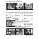
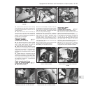
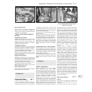
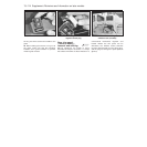
80 Prise free the lamp unit from its aperture
in the roof panel using a thin-bladed
screwdriver. The lamp bulb can be inspected
by untwisting the holder and withdrawing it
from the rear of the unit (photos). Extract the
bulb from the holder if it requires renewal.
81 To remove the lamp switch from the
panel, reach through the lamp aperture and
press it free from the roof panel (photo).
Detach the wiring connectors.
82 To remove the clock, reach through the
lamp aperture and undo the retaining screws
(photo). Withdraw the clock and detach the
wiring connectors.
13•108 Supplement: Revisions and information on later models
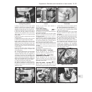
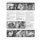
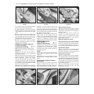
15.69B . . . and withdraw the heater control
panel
15.69A . . . undo the retaining screws
(arrowed)
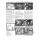
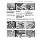
15.68 Remove the control knobs . . .
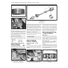
15.63 . . . and withdraw the auxiliary
control panel
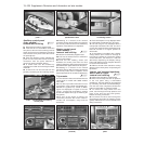
15.62 Prise free the trim covers for access
to retaining screws . . .
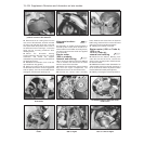
15.59B . . . and disconnect the
speedometer cable
15.59A . . . withdraw the instrument
panel . . .