


3.4 Removing the caliper unit
1 General description
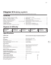
The braking system is of four wheel
hydraulic type with discs on the front wheels
and drums on the rear.
The hydraulic system is of dual-circuit type
and incorporates a pressure regulator valve to
limit pressure to the rear brakes during heavy
braking to prevent rear wheel lock up.
A vacuum servo unit is fitted to some
models.
The handbrake is mechanically operated on
the rear wheels.
2 Maintenance
1
1 At the weekly service check, inspect the
fluid level in the master cylinder reservoir.
Topping up should only be required at very
infrequent intervals and should only be
necessary owing to the need for extra fluid in
the hydraulic system caused by wear of the
friction material of the disc pads and shoe
linings.
2 The need for frequent or regular topping up
will be due to a leak in the system, probably
from a hydraulic cylinder seal or a flexible
hose. Correct the problem immediately.
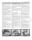
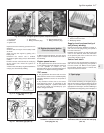
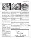
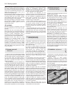
3 Use only clean new fluid for topping up. lt
must be of the specified type and have been
stored in a closed container and not have
been shaken for at least 24 hours (photo).
4 At regular intervals, check the hoses and
pipelines for condition. Adjust the handbrake
if the lever travel becomes excessive. Check
the condition and security of the brake servo
vacuum hose. All these operations are
described later in this Chapter.
3 Disc pads -
inspection and renewal
2
1 Jack up the front of the car and remove the
roadwheels.
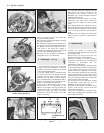
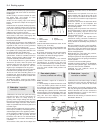
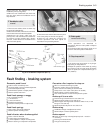
2 Extract the spring clips and slide out the
locking blocks (photos).
3 On SX versions, carefully disconnect the
wear sensor lead connecting plug.
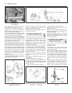
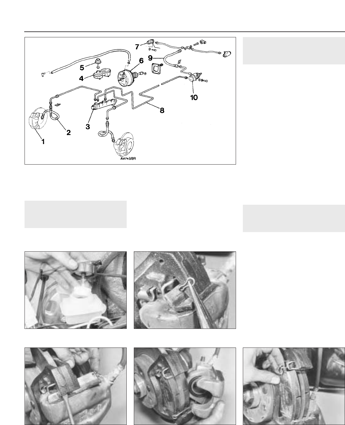
4 Lift the caliper body from the disc and
inspect the thickness of the friction material
on each pad (photo). If it is 1.5 mm (0.06 in) or
less, renew the pads.
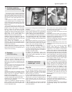
5 Withdraw the pads and the anti-rattle
springs.
6 Brush away any dust and dirt from the
caliper, taking care not to inhale the dust - this
contains asbestos and is thus potentially
injurious to health.
7 As the new pads are thicker than the old
ones, the caliper piston must be depressed
8•2 Braking system
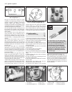
3.8A Disc pad and anti-rattle spring
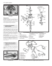
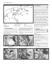
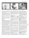
Fig. 8.1 Components of the braking system (LHD shown) (Sec 1)
1 Caliper
2 Hose
3 Master cylinder
4 Fluid reservoir
5 Cap and fluid level sensor
6 Vacuum servo unit
7 Rear wheel cylinder
8 Pipeline
9 Hose
10 Pressure regulating valve
3.2B Removing a locking block
3.2A Removing a disc pad locking block
clip
2.3 Fluid reservoir cap and float for
warning switch