


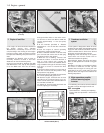
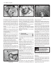
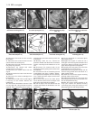
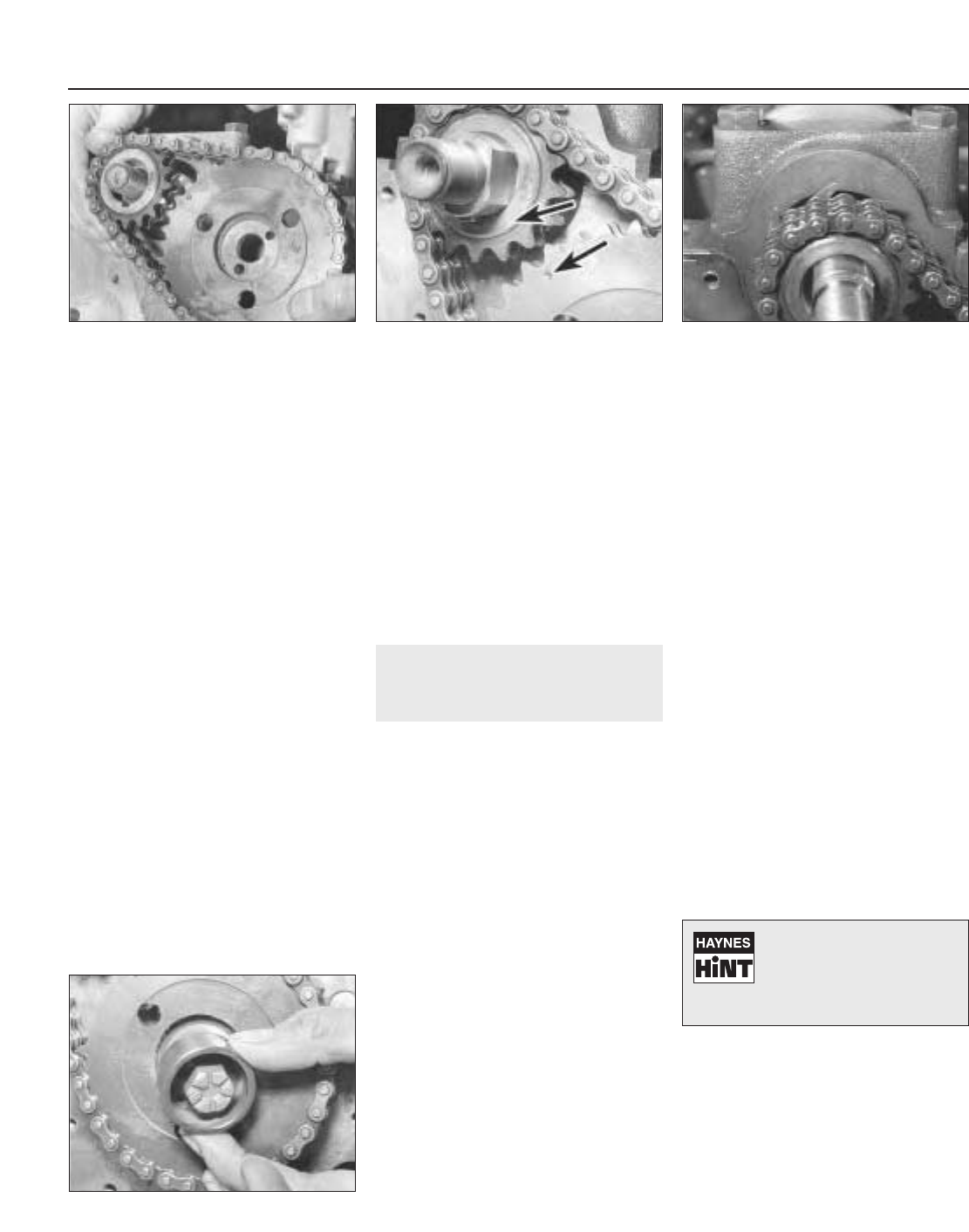
13 Engage the timing chain with the teeth of
the crankshaft sprocket. Then locate the
camshaft sprocket within the upper loop of
the chain in such a way that when the
sprocket is pushed onto the camshaft, the
timing marks will be in alignment. Make sure
that the self-tensioning links are on the inside
of the chain against the cylinder block
(photos).
14 Place the camshaft sprocket onto the
camshaft so that its positioning dowel
engages.
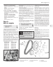
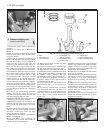
15 Secure the camshaft sprocket by fitting
the special cam, that drives the fuel pump, on
its locating dowel. Fit the camshaft sprocket
retaining bolt (photo).
16 Tighten the sprocket bolt to the specified
torque.
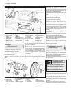
17 If the timing cover oil seal showed signs of
leaking before engine overhaul the old seal
should be removed and a new one fitted.
18 Using a screwdriver, carefully remove the
old oil seal, working from the rear of the cover.
Fit the new seal making sure it is inserted
squarely, and tap home with a hammer.
19 Lubricate the oil seal with engine oil.
20 With all traces of old gasket and jointing
compound removed from the timing cover
and cylinder block mating faces, smear a little
grease onto the timing cover mating face and
fit a new gasket in position.
21 Fit the timing cover to the cylinder block
and finger tighten the securing bolts, and
spring washer. Ensure that the fuel pump
pushrod bush is in place in the cover.
22 Wipe the hub of the pulley and carefully
place into position on the crankshaft. It should
locate on the Woodruff key. It may be
necessary to adjust the position of the timing
cover slightly in order to centralise the oil seal
relative to the pulley hub.
23 Tighten the timing cover securing bolts in
a diagonal and progressive manner.
24 Tighten the crankshaft pulley nut to the
specified torque again holding the crankshaft
against rotation as previously described
(paragraph 2) this Section.
25 Refit the fuel pump and alternator
drivebelt.
7 Cylinder head -
removal and refitting
3
1 For safety reasons, disconnect the battery
negative lead.
2 Refer to Chapter 2 and drain the cooling
system.
3 Refer to Chapter 3 and remove the
carburettor, air cleaner and spacer block.
4 Undo and remove the five nuts and
washers securing the exhaust manifold and
hot air ducting to the cylinder head.
5 Detach the cable from the temperature
indicator sender unit.
6 Refer to Chapter 4 and disconnect the
distributor LT lead and the coil HT lead.
7 Refer to Chapter 2 and remove the
thermostat housing from the cylinder head.
8 Disconnect the coolant hoses from the
cylinder head.
9 Note the electrical connections to the rear
of the alternator and disconnect them.
10 Disconnect the mounting and adjuster link
bolts and remove the alternator from the
engine.
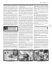
11 Unscrew the four nuts securing the rocker
cover to the top of the cylinder head and lift
away the spring washers and metal packing
pieces. Remove the rocker cover and cork
gasket.
12 Unscrew the four rocker pedestal
securing nuts in a progressive manner. Lift
away the four nuts and spring washers and
ease the valve rocker assembly from the
cylinder head studs.
13 Remove the pushrods, keeping them in
the relative order in which they were removed.
The easiest way to do this is to push them
through a sheet of thick paper or thin card in
the correct sequence.
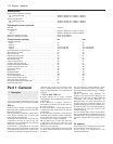
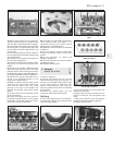
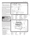
14 Unscrew the cylinder head securing bolts
half a turn at a time in the reverse order to that
shown in Fig. 1.7; don’t forget the one within
the inlet manifold. When all the bolts are no
longer under tension they may be unscrewed
from the cylinder head one at a time. This will
also release a section of the cooling system
pipe secured by two of the bolts. All the bolts
have washers.
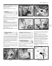
15 The cylinder head may now be lifted off. If
the head is jammed, try to rock it to break the
seal. Under no circumstances try to prise it
apart from the cylinder block with a
screwdriver or cold chisel as damage may be
done to the faces of the head or block. If this
or the Hint, fail to work, strike the head
sharply with a plastic headed hammer, or with
a wooden hammer, or with a metal hammer
with an interposed piece of wood to cushion
the blows. Under no circumstances hit the
head directly with a metal hammer as this may
cause the casting to fracture. Several sharp
taps with the hammer, at the same time
pulling upwards, should free the head. Lift the
head off and place on one side.
16 The cylinder head may now be de-
carbonised or dismantled, refer to Section 17.
Refitting
17 After checking that both the cylinder block
and cylinder head mating surfaces are
perfectly clean, generously lubricate each
cylinder with engine oil.
18 Always use a new cylinder head gasket as
the old gasket will be compressed and not
capable of giving a good seal.
1•10 903 cc engine
6.15 Fitting fuel pump drive cam and
sprocket bolt
6.13C Self-tensioning links on inside of
chain
6.13B Timing mark alignment6.13A Fitting the sprockets and timing
chain
If the head will not readily
free, turn the crankshaft.
The compression generated
in the cylinders will often
break the gasket joint