


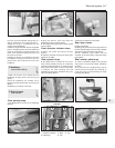
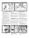

paintwork should the drill slip. Three methods
of making the hole are in use:
a) Use a hole saw in the electric drill. This is,
in effect, a circular hacksaw blade
wrapped round a former with a centre
pilot drill.
b) Use a tank cutter which also has cutting
teeth, but is made to shear the metal by
tightening with an Allen key.
c) The hard way of drilling out the circle is
using a small drill, say 1/8 in (3 mm), so
that the holes overlap. The centre metal
drops out and the hole is finished with
round and half-round files.
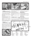
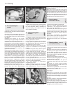
14 Whichever method is used, the burr is
removed from the body metal and paint
removed from the underside. The aerial is fitted
tightly ensuring that the earth fixing, usually a
serrated washer, ring or clamp, is making a
solid connection. This earth connection is
important in reducing interference. Cover any
bare metal with primer paint and topcoat, and
follow by underseal if desired.
15 Aerial feeder cable routing should avoid
the engine compartment and areas where
stress might occur, eg under the carpet where
feet will be located.
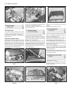
Loudspeakers
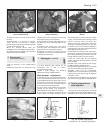
16 A mono speaker may be located under
the facia panel beneath the glovebox.
17 Provision is made for twin speakers within
the door tidy bins or under the rear shelf
mountings.
18 Speakers should be matched to the
output stage of the equipment, particularly as
regards the recommended impedance. Power
transistors used for driving speakers are
sensitive to the loading placed on them.
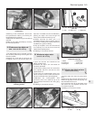
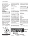
31 Electrically-operated front
door windows
3
1 The electrically-operated front door
windows are controlled by switches on the
centre console or in the door armrest
(depending on model). The regulator motor
and cable are located within the door cavity.
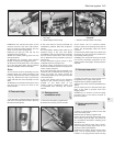
2 To gain access to the assembly, remove
the door trim panel as described in Chap-
ter 12.
3 Disconnect the wiring plug (1) (Fig. 9.11).
4 Release the bolts which connect the power
lift to the glass mounting.
5 Remove the bolts which hold the lift
assembly to the door.
6 The motor and glass mounting may be
disconnected from the cable guide and sleeve
and any faulty components renewed.
7 When refitting the assembly to the door,
make sure that the window glass slides
smoothly before fully tightening the cable
guide bolts. Refer to Section 10 for details of
system fuses and relays.
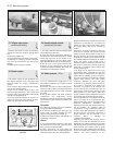
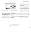
32 Central door locking system
1
1 The doors are locked simultaneously from
the outside by turning the key in either
direction.
2 The doors can be locked from inside the car
in the following ways:
All doors locked or unlocked - depress or lift
a front door lock plunger knob.
One rear door locked or unlocked - depress
or lift a rear door lock plunger knob.
Electrical system 9•11
Fig. 9.9 Door speaker mounting (Sec 30) Fig. 9.10 Rear speaker mounting (Sec 30)
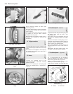
Fig. 9.13 Central door locking system
components (Sec 32)
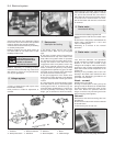
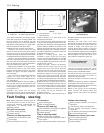
Fig. 9.12 Power operated window
components (Sec 31)
Fig. 9.11 Power-operated window motor
(Sec 31)
1 Connector plug
1 Electric motor
2 Glass mounting
3 Cable guide
4 Cable
5 Cable sleeve
1 Solenoid
2 Lock relay lever
3 Link rod
4 Exterior handle
lever
9