


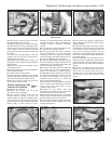

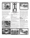
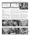
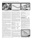
32 Fit the hot air collector plate for the air
cleaner (photo).
33 Refer to Section 10 and fit the distributor.
34 Bolt on the timing belt cover.
35 Fit the camshaft cover, using a new
gasket unless the original one is in perfect
condition.
Engine/transmission -
reconnection and refitting #
36 Locate the engine in an upright position
on wooden blocks to allow for the greater
depth of the transmission flywheel housing
when it is joined to the engine.
37 Make sure that the clutch driven plate has
been centralised, offer the transmission to the
engine and locate the flywheel housing on the
single stud and dowels.
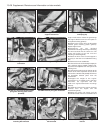
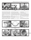
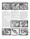
38 Tighten the connecting bolts to specified
torque, having located the lifting eye (photo).
39 Bolt on the starter motor.
40 Refit the cover plate to the flywheel
housing, but do not insert the lower bolts at
this stage as they retain the support bracket
for the gearchange rod.
41 The engine and transmission are now
ready for refitting. The operations are a direct
reversal of the operations described earlier,
but observe the following points.
42 Have the engine/transmission perfectly
horizontal and suspended on the hoist.
43 Lower it into position very slowly until it is
possible to engage the driveshaft inboard
joints with the transmission.
44 Continue lowering until the driveshafts
can be fully engaged and the mountings
reconnected. Remove the hoist.
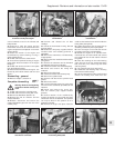
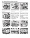
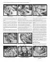
45 Tighten all nuts and bolts to the specified
torque. Note the method shown for
connecting the gearchange rod ball socket
using pliers (photo).
46 Refill the engine with oil and coolant and
replenish the transmission oil.
Initial start-up after major
overhaul
47 Refer to Chapter 1, Section 45.
6 Engine -
1301 cc Turbo ie
PART A: GENERAL
Description
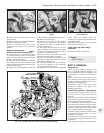
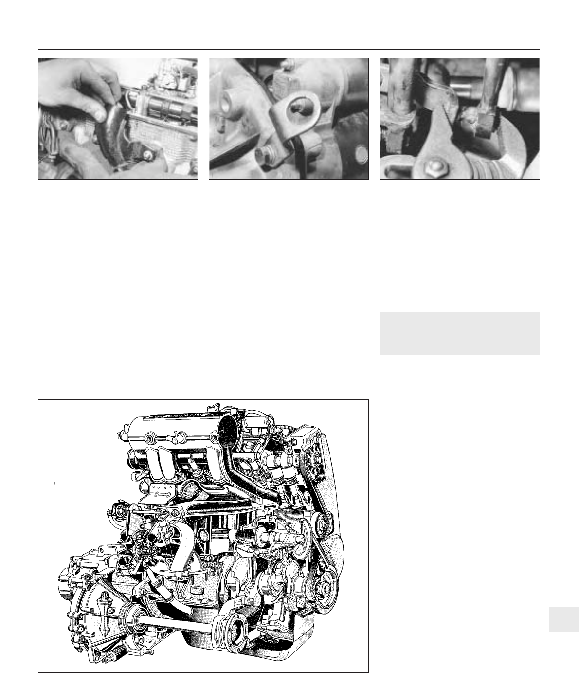
1 This engine is similar in design to the
1301 cc engine described in Chapter 1, but
the fuel and ignition systems are different, and
a turbocharger, oil cooler and intercooler are
fitted.
2 Many dimensions and tolerances have
been altered for this engine, and reference
should be made to the Specifications at the
beginning of this Supplement.
3 Operations which differ from those
described in Chapter 1 are given in the
following sub-Sections.
Lubrication system - description
4 The lubrication system differs from the
non-Turbo 1301 cc engine in the following
respects.
5 An oil cooler is fitted, which comprises a
matrix with inlet and outlet hoses connected
to the oil filter cartridge mounting base.
6 A thermostatic control switch is fitted,
which diverts the oil flow through the matrix
only at oil temperatures above 84ºC (183ºF).
Note that a faulty switch will require renewal
of the complete oil filter mounting base.
7 Special oil spray nozzles are located in the
crankcase main bearing webs, to cool the
underside of the pistons.
8 The ball-type valves in the nozzles open
when the engine oil pressure reaches 1.2 bars
(17.4 lbf/in
2
).
9 An oil pressure sender unit is screwed into
Supplement: Revisions and information on later models 13•33
5D.45 Connecting ball socket type
gearchange rod
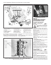
5D.38 Lifting eye on flywheel housing
flange
5D.32 Air cleaner hot air collector plate
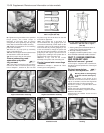
Fig. 13.10 Cutaway view of the 1301 cc Turbo ie engine (Sec 6A)
13