


16 Engine -
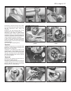
complete dismantling
3
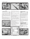
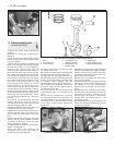
1 Unbolt and remove the rocker cover.
2 Unscrew the rocker pedestal securing nuts
and lift away the rocker assembly.
3 Remove the pushrods, keeping them in
their original fitted order.
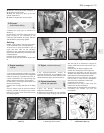
4 Remove the cylinder head as described in
Section 7. Remove the dipstick and guide
tube.
5 Turn the engine on its side and unbolt and
remove the sump pan.
6 Remove the piston/connecting rods as
described in Section 9.
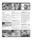
7 Unscrew and remove the crankshaft pulley
nut. To prevent the crankshaft rotating while
this is done, either jam the flywheel ring gear
or place a block between a crankshaft
counterweight and the inside of the
crankcase.
8 Unbolt and remove the timing cover.
9 Remove the timing chain and sprockets as
described in Section 6.
10 Unbolt and remove the oil pump as
described in Section 10.
11 Unscrew and remove the camshaft front
bearing lockscrew noting that the chamfer on
the bearing is on the inboard side.
12 Withdraw the camshaft, taking great care
not to damage the bearings with the cam
lobes.
13 Lift out the cam followers and keep them
in their originally fitted sequence.
14 Unbolt and remove the flywheel. Jam the
ring gear teeth to prevent rotation.
15 Remove the engine rear plate.
16 Turn the cylinder block so that it is
standing upside down.
17 Unbolt and remove the crankshaft rear oil
seal carrier. Note the sump fixing studs.
18 The main bearing caps should be marked
1, 2 and 3 but if they are not, centre punch
them and note which way round they are
located.
19 Unscrew the main bearing cap bolts
progressively.
20 Remove the bearing caps and half shells.
If the shell bearings are to be used again,
keep them with their respective caps.
21 Note the semi-circular thrust washers on
either side of the centre main bearing which
control crankshaft endfloat.
22 Lift the crankshaft from the crankcase.
23 Remove the bearing shells from the
crankcase and mark them as to position if
they are to be used again.
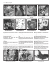
17 Cylinder head - dismantling
and decarbonising
4
1 The exhaust manifold and rocker gear will
have been removed from the cylinder head
during removal (see Section 7).
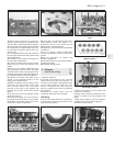
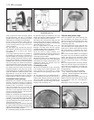
2 The valves should now be removed using a
universal valve spring compressor.
3 Compress the first valve spring and extract
the split cotters.
4 Gently release the compressor, take off the
spring retaining cap, the valve spring and the
spring seat. Remove the valve. Keep the valve
with its associated components together and
in numbered sequence so that they can be
returned to their original positions.
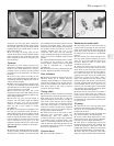
5 A small box with divisions is useful for this
purpose. Remove and discard the valve stem
oil seals.
6 Remove the other valves in a similar way.
7 Bearing in mind that the cylinder head is of
1•16 903 cc engine
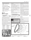
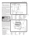
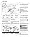
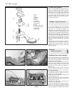
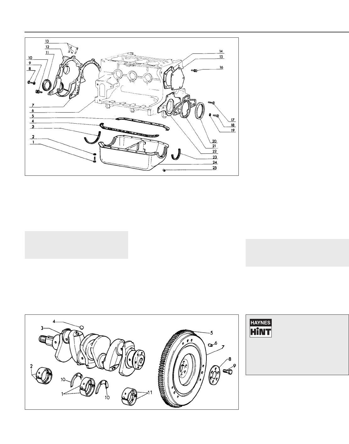
Fig. 1.23 Timing cover, sump pan and oil seals (Sec 16)
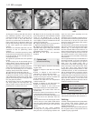
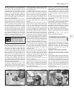
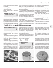
Fig. 1.24 Crankshaft and flywheel (Sec 16)
1 Sump pan bolt
2 Washer
3 Sealing strip
4 Side gasket
5 Side gasket
6 Block/crankcase
7 Gasket
8 Bolt
9 Washer
10 Bolt and washer
11 Crankshaft front oil
seal
12 Timing cover
14 Gasket
13 Fuel pump studs
and bush
15 Cover plate
16 Bolt and washer
17 Bolt
18 Bolt
19 Washer
20 Crankshaft rear oil
seal
21 Oil seal carrier
22 Gasket
23 Sealing strip
24 Sump pan
25 Drain plug
1 Centre main
bearing shells
2 Front main bearing
shells
3 Crankshaft
4 Plug
5 Starter ring gear
6 Dowel
7 Flywheel
8 Thrust plate
9 Bolt
10 Thrust washers
11 Rear main bearing
shells
If the valve spring refuses to
compress, do not apply
excessive force, but remove
the compressor and place a
piece of tubing on the spring retainer
and strike it a sharp blow to release the
collets from the valve stem. Refit the
compressor and resume operations
when the collets should come out.