


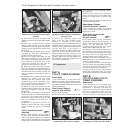
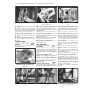
14B.54 Master cylinder/vacuum servo
located next to the coolant expansion tank
(1301 cc Turbo ie model)
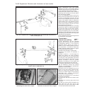
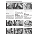
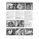
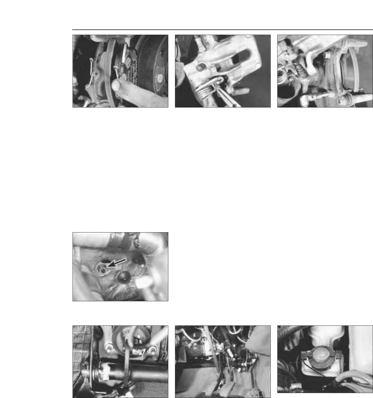
29 Fit the new pads, complete with anti-rattle
springs (photo).
30 Refit the caliper using new self-locking
bolts, or if not available, apply thread-locking
fluid to clean threads of the original bolts.
Tighten the bolts to the specified torque.
31 Apply the brake pedal several times to
bring the disc pads up against the disc.
32 Top up the brake fluid reservoir if
necessary.
33 Check the adjustment of the handbrake.
34 Refit the roadwheels and lower the car to
the ground.
Rear disc caliper -
removal, overhaul and
refitting ¢
35 Carry out the operations described in
paragraphs 25 to 27.
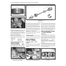
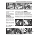
36 Disconnect the handbrake cable from the
caliper. To do this, grip the cable nipple and
pull it until the cable can be slipped out of its
lever groove (photo). If necessary, slacken the
cable adjustment.
37 Using a pair of pliers or similar tool, turn
the piston in an anti-clockwise direction until it
can be removed from the cylinder.
38 Having obtained a repair kit, renew the
seal and dust excluder.
39 Reassemble the piston to the cylinder,
turning it clockwise as far as it will go.
40 Reconnect the handbrake cable.
41 Carry out the operations described in
paragraphs 30 to 32.
Rear brake disc -
inspection, renovation
or renewal ™
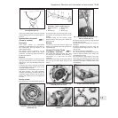
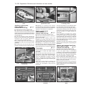
42 The operations are as described in
Chapter 8, Section 6, but the caliper bracket
fixing bolts are of the socket-headed type and
thread-locking fluid is used, not lockplates
(photo).
Pressure regulating valve
43 The valve renewal and adjustment
operations are described in Chapter 8,
Section 10, but the luggage compartment
should be loaded with 45 kg and the load
applied to the bracket eye should be 11 kg.
Brake pedal -
removal and refitting #
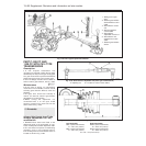
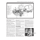
44 The brake master cylinder and vacuum
servo are mounted on the left-hand side of the
engine compartment rear bulkhead. In conse-
quence, the brake pedal on right-hand drive
cars operates through a cross-shaft, which is
located underneath the facia panel inside the
car.
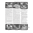
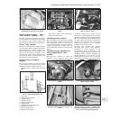
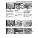
45 The cross-shaft is supported in two
brackets, whose mounting nuts can be
reached through cut-outs in the insulation on
the engine compartment rear bulkhead (photo).
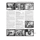
46 To remove the cross-shaft, working inside
the car, take off the cover from the left-hand
end of the shaft, and then disconnect the
servo pushrod from the crankarm on the
cross-shaft (photo).
47 Disconnect the brake pedal from the
right-hand crankarm on the cross-shaft
(photo).
48 Disconnect the accelerator pedal by
extracting the split pin which secures its pivot
spindle.
49 The cross-shaft may now be removed
after extracting the cotter pin from the
left-hand end of the shaft.
50 Push the shaft first to the right, and then
to the left, to release it from its brackets.
51 Alternatively, the cross-shaft, complete
with brackets, may be removed as an
assembly if the bulkhead nuts are unscrewed.
52 Removal of the brake and clutch pedals is
described in Chapter 5, Section 4, but note
that on hydraulic clutch models, the master
cylinder will also require removal as described
in Section 11 of this Chapter.
53 Refitting is a reversal of the removal
procedure.
13•102 Supplement: Revisions and information on later models
14B.47 Right-hand end of brake pedal
cross-shaft
14B.46 Left-hand end of brake pedal
cross-shaft
14B.45 Brake pedal cross-shaft fixed nut
(arrowed) on engine compartment rear
bulkhead
14B.42 Unscrewing a rear caliper bracket
bolt
14B.36 Disconnecting the handbrake cable
from the caliper lever
14B.29 Rear disc pad