


Engine oil cooler -
removal and refitting ¡
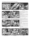
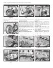
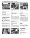
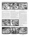
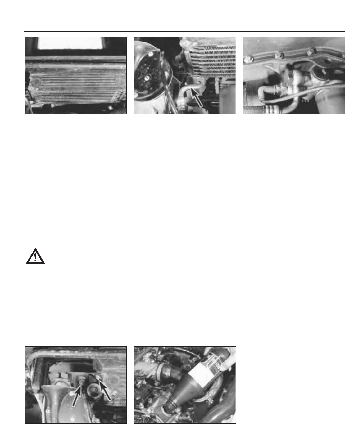
23 The oil cooler is mounted behind the front
bumper/spoiler (photo).
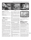
24 Disconnect the oil flow and return hoses,
either from the cooler or the oil filter cartridge
mounting base. Be prepared for some
leakage of oil (photos).
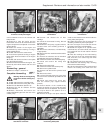
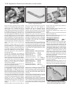
25 Unscrew the mounting bolts and remove
the oil cooler heat exchanger (photo).
26 When refitting, make sure that the banjo
union sealing washers are in good condition.
PART C: ENGINE REMOVAL,
DISMANTLING, REASSEMBLY
AND REFITTING
Engine/transmission -
removal and separation #
Warning: Refer to the beginning
of Section 9 before starting any
work.
1 Refer to Chapter 1, Section 35, and carry
out the operations described in paragraphs 1
to 11.
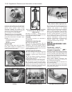
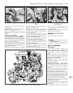
2 Disconnect the excessive air pressure
switch from the inlet manifold.
3 Disconnect the ducts and remove the
airflow meter.
4 Disconnect the leads from the spark plugs
and the distributor LT connector, and unbolt
and remove the distributor from the rear end
of the camshaft carrier.
5 Disconnect the fuel return hose from the
pressure regulator.
6 Disconnect the fuel inlet hose from the
injector rail.
7 Disconnect the wiring plugs from the fuel
injectors.
8 Disconnect the leads from the oil pressure
sender unit, the low oil pressure switch and
the coolant temperature switch.
9 Remove the hose/pipe assemblies from the
intercooler.
10 Disconnect the throttle control rod at the
balljoint.
11 Disconnect the hoses and ducts from the
turbocharger and the mechanical bypass
valve.
12 Disconnect the leads from the engine
speed and anti-knock sensors.
13 Raise the front of the car and support it
securely. As the engine/transmission will
eventually be lowered to the floor, make sure
that there is sufficient clearance under the
front end for the assembly to be withdrawn. If
the car is over an inspection pit, then the car
need only be raised enough to lift the
roadwheels from the floor.
14 Remove the front roadwheels.
15 Disconnect the transmission earth cable.
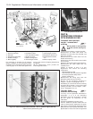
16 Working under the car, remove the engine
shields from under the wheel arches.
17 Remove the engine oil cooler, and the
intercooler.
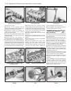
18 Unscrew the fixing screws and disconnect
the driveshafts from the flanges at the
transmission final drive. The right-hand
driveshaft will not release until the upper bolt
on the suspension strut-to-hub carrier clamp
has been removed, and the hub assembly
tilted downwards.
19 Disconnect the exhaust downpipe from
the manifold, and then remove the front
section of the exhaust system.
20 Disconnect the coolant return pipe from
the turbocharger.
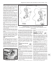
21 Disconnect the gearchange control rods
from the transmission selector rod. Do this by
unscrewing the self-locking nut from the bolt
which connects the clevis fork.
22 Attach suitable lifting gear to the engine
lifting eyes, and take the weight of the
engine/transmission.
23 Disconnect the left-front, centre-rear and
the right-hand engine/transmission mountings.
Do this by removing the bolts from the
diamond-shaped mounting plates there is no
need to disturb the flexible mounting centre
bolts.
24 Lower the engine/transmission to the floor
and withdraw it from under the car.
25 Carry out the operations described in
Chapter 1, Section 35, paragraphs 27 to 31.
Engine dismantling and
reassembly
26 The operations are essentially as
described for the 1301 cc engine in Chapter 1,
but reference must be made to Sections 9
and 10 of this Chapter for the procedures for
removing and refitting the components of the
fuel injection, turbocharger and ignition
systems.
Engine/transmission -
reconnection and refitting
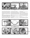
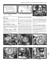
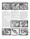
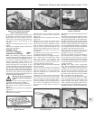
27 The operations are a reversal of those
described in paragraphs 1 to 25, but
otherwise the following (photo).
a) Tighten all nuts and bolts to the specified
torque.
b) Use a new gasket at the exhaust
downpipe-to-manifold flange.
c) Check and adjust the clutch pedal travel.
d) Refill the cooling system.
e) Refill the engine and transmission with oil.
f) Reconnect the battery, negative lead
last.
13•36 Supplement: Revisions and information on later models
6C.27 Filling the engine with oil6B.25 Oil cooler mounting bolts (arrowed)
6B.24B Connections at oil filter cartridge
mounting base
6B.24A Oil cooler pipe connection
(arrowed)
6B.23 Oil cooler