


11 Clutch
Clutch pedal - adjustment
(cable clutch) ¡
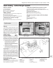
1 The method of adjusting the clutch has
been revised.
2 Fully depress the clutch pedal two or three
times.
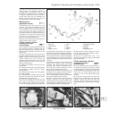
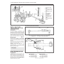
3 Using a suitable measuring stick placed in
contact with the floor panel (carpet peeled
back), measure dimension “X” in Fig. 13.87.
This dimension must be taken between the
centre of the pedal pad and the floor, first with
the pedal in the fully depressed position, and
then in the fully released position.
4 The dimension measured should fall within
the range quoted in the Specifications for this
Supplement.
5 Any adjustment which may be required
should be carried out by slackening the
locknut on the cable at the release lever (on
top of the gearbox) and turning the adjusting
nut. Tighten the locknut on completion.
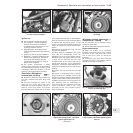
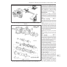
Hydraulic clutch - description
6 Some later models are fitted with an
hydraulically operated clutch in place of the
cable operated type. The main components of
the system are a master cylinder, with
separate hydraulic fluid reservoir, and the
operating cylinder. The master cylinder is
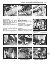
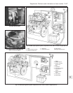
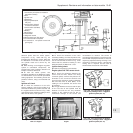
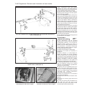
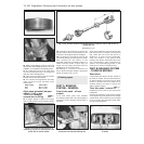
Distributor (Digiplex Z) -
removal and refitting #
70 Proceed as described in paragraphs 14
to 21. When refitting the distributor, ensure that
the engine is still set at the TDC position. Engage
the rotor arm into position on the shaft so that its
lug engages in the slot in the top end of the drive
spindle. Align the rotor arm with the reference
slot on the edge of the distributor housing as
shown in Fig. 13.85, then fit the distributor into
position and secure with the retaining nuts
(photo). As previously mentioned, the fine timing
is made automatically through the ECU.
Spark plugs and HT leads -
general
71 Copper-cored spark plugs are now fitted
to all models. The recommended types are
given in the Specifications Section of this
Supplement.
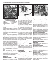
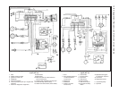
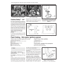
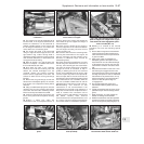
72 The HT lead connection sequence to the
distributor cap on the 999 and 1108 cc
engines is shown in Fig. 13.86. That for the
1301 cc Turbo ie is as shown (photo).
13•92 Supplement: Revisions and information on later models
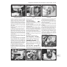
Fig. 13.87 Clutch pedal adjustment
diagram - cable clutch (Sec 11)
For dimension “X” , refer to Specifications
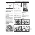
Fig. 13.86 HT lead connections on distributor cap of the 999 and 1108 cc engines (Sec 10)
Fig. 13.85 Rotor arm must align with
slot (1) in distributor housing when refitting
distributor - Digiplex 2 ignition system
(Sec 10)
10.72 HT lead connecting sequence on the
1301 cc Turbo ie engine
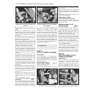
10.70 Ignition distributor and HT lead
connections on the 1372 cc ie engine
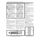
Fault finding - Microplex ignition system
Starter motor turns but engine will not start
ⅥⅥExcessive TDC sensor gap
ⅥⅥ Engine speed or TDC sensors short-circuited
ⅥⅥ Faulty ECU
ⅥⅥ ECU multipin contacts corroded
ⅥⅥ Defective ignition coil
ⅥⅥ Defective ignition switch
ⅥⅥ ECU terminal 8 cable faulty
Engine firing on three cylinders
ⅥⅥ Faulty spark plug
ⅥⅥ Distributor cap cracked
ⅥⅥ Faulty HT cable
Loss of power, excessive fuel consumption
ⅥⅥ TDC sensor incorrectly located
ⅥⅥ Fault in ECU advance angle facility