


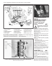
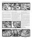
separately, after the ten main bolts (see
Fig. 13.13).
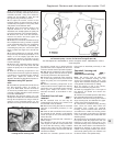
Piston rings
14 The piston rings comprise two
compression rings marked TOP, and an oil
control ring.
15 Cross-sections and fitting details are
shown in Fig. 13.14.
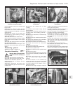
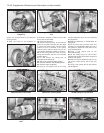
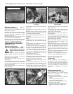
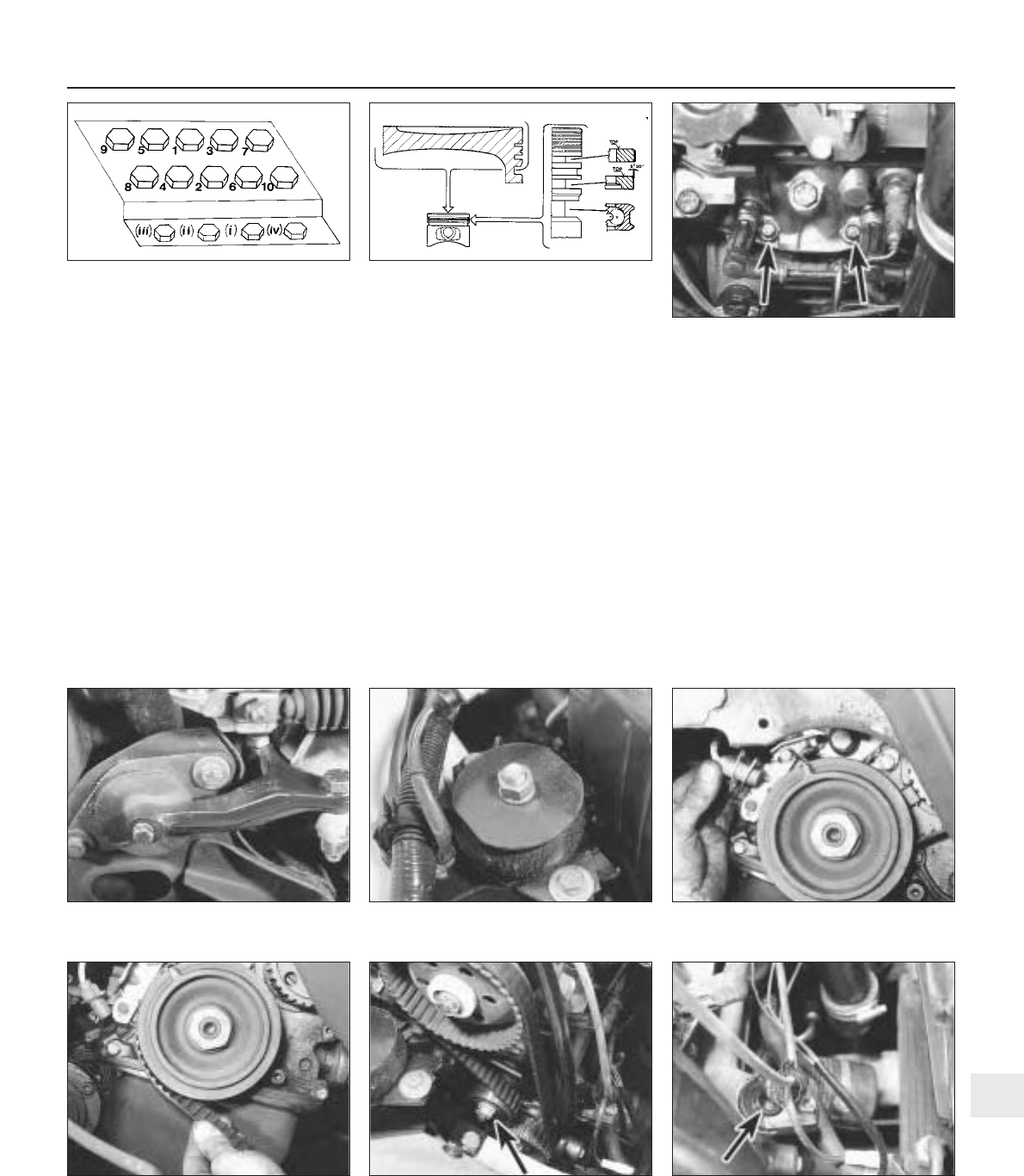
Engine mountings - renewal
16 The operations are essentially as
described in Section 33 of Chapter 1, but note
the design and fixings of the individual
mountings used on the turbocharged engine
(photos).
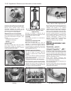
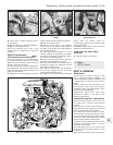
Timing belt - renewal #
17 The operations described in Chapter 1,
Section 28 generally apply, but the following
differences should be noted.
18 Remove the engine compartment
right-hand shield. This is secured by plastic
clips. To remove a clip, push out its centre
pin.
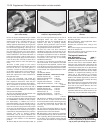
19 The TDC sensor must be unbolted to
provide room to remove and refit the timing
belt, which can be carried out without
having to remove the crankshaft pulley
(photos).
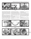
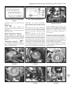
20 The belt tensioner on later versions
does not incorporate a spring, but is of
eccentric centre bolt hole type. Have the
pulley bolt released, and tension the belt by
turning the pulley using a pin wrench or
circlip pliers in the two holes provided.
Keep the tension applied while the lockbolt
is tightened. Turn the crankshaft through
two complete turns, and then check the belt
tension. With moderate finger and thumb
pressure, the belt should just twist through
90º when gripped at the mid-point of its
longest run (photo). Note: This procedure
serves only as a rough guide to setting the
belt tension - having it checked by a FIAT
dealer at the earliest opportunity is
recommended.
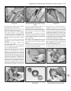
Oil pump drivegear cover plate
21 Due to the fact that the distributor is
driven from the end of the camshaft, the oil
pump gear does not have an extension to
drive the distributor, which would be the case
if it was mounted on the crankcase.
22 The crankcase aperture is therefore
covered by a plate and gasket, together with a
wiring clip (photo).
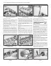
Supplement: Revisions and information on later models 13•35
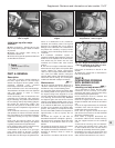
6B.13 Two of the four additional cylinder
head bolts (arrowed)
Fig. 13.14 Piston ring arrangement on the
1301 cc Turbo ie engine (Sec 6B)
Fig. 13.13 Cylinder head bolt tightening
sequence on the 1301 cc Turbo ie engine
(Sec 6B)
6B.22 Distributor drive hole cover plate
(arrowed)
6B.20 Belt tensioner pulley locknut
(arrowed)
6B.19B Removing the timing belt
6B.19A Removing the TDC sensor6B.16B Engine/transmission right-hand
mounting
6B.16A Engine/transmission centre
mounting
13