


c) If the engine develops a misfire, do not
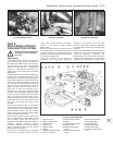
drive the car at all (or at least as little as
possible) until the fault is cured - the
misfire will allow unburned fuel to enter
the converter, which will result in its
overheating, as noted above.
d) DO NOT push- or tow-start the car - this
will soak the catalytic converter in
unburned fuel, causing it to overheat
when the engine does start - see b)
above.
e) DO NOT switch off the ignition at high
engine speeds - if the ignition is switched
off at anything above idle speed,
unburned fuel will enter the (very hot)
catalytic converter, with the possible risk
of its igniting on the element and
damaging the converter.
f) DO NOT use fuel or engine oil additives -
these may contain substances harmful to
the catalytic converter.
g) DO NOT continue to use the car if the
engine burns oil to the extent of leaving a
visible trail of blue smoke - the unburned
carbon deposits will clog the converter
passages and reduce its efficiency; in
severe cases the element will overheat.
h) Remember that the catalytic converter
operates at very high temperatures and
the casing will become hot enough to
ignite combustible materials which brush
against it. DO NOT, therefore, park the car
in dry undergrowth, over long grass or
piles of dead leaves.
i) Remember that the catalytic converter is
FRAGILE - do not strike it with tools
during servicing work, take great care
when working on the exhaust system,
ensure that the converter is well clear of
any jacks or other lifting gear used to raise
the car and do not drive the car over
rough ground road humps, etc., in such a
way as to ground the exhaust system.
j) In some cases, particularly when the car is
new and/or is used for stop/start driving, a
sulphurous smell (like that of rotten eggs)
may be noticed from the exhaust. This is
common to many catalytic
converter-equipped cars and seems to be
due to the small amount of sulphur found
in some petrols reacting with hydrogen in
the exhaust to produce hydrogen sulphide
(H
2
S) gas; while this gas is toxic, it is not
produced in sufficient amounts to be a
problem. Once the car has covered a few
thousand miles the problem should
disappear - in the meanwhile a change of
driving style or of the brand of petrol used
may effect a solution.
k) The catalytic converter, used on a
well-maintained and well driven car,
should last for at least 50 000 miles
(80 000 km) or five years - from this point
on, careful checks should be made at all
specified service intervals on the CO level
to ensure that the converter is still
operating efficiently - if the converter is no
longer effective it must be renewed.
Fuel evaporation control system
- general
76 As mentioned earlier, fuel evaporation is
contained within the system. In high outdoor
temperatures, when the vehicle is parked for a
period of time, the fuel in the tank evaporates,
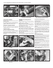
building up pressure. When the pressure builds
up to a predetermined level a vent valve opens
to allow the vapours to pass on to and absorbed
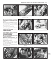
by a carbon filter. However, if extreme pressure
or vacuum should build up, a two way safety
valve opens to allow external venting.
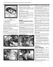
77 If the safety valve needs replacing, note
that it must be fitted correctly. The black end
should be connected to the fuel tank and the
blue to the carbon filter.
78 The vapours in the carbon filter are
flushed by warm air passing through the filter
on to a ECU controlled vapour cut-off
solenoid.
79 The cut-off solenoid is closed when
starting the engine and opens to allow
vapours to be drawn into the inlet manifold,
through a second solenoid. If the cut-off
solenoid needs replacing ensure that the
black arrow on the casing is pointing towards
the inlet manifold.
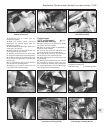
80 The second solenoid, known as an Elbi
solenoid, is closed when the engine is turned
off, thus preventing engine run-on. The side
facing connection is for the inlet manifold
pipe.
PART E:
BOSCH L3.1/2 JETRONIC
FUEL INJECTION SYSTEMS
Warning: Refer to the beginning
of this Section before starting
any work.
Description
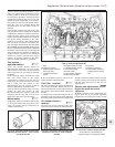
1 A Bosch L3.1 (or L3.2, as fitted from 1992)
Jetronic fuel injection system is fitted to the
1372 cc Turbo ie engine. The system circuit
and main component locations are shown in
Figs. 13.48 and 13.49.
2 The L3.1/2 Jetronic system is a multi-point
fuel injection (MPi) system. It operates in a
similar manner to that of the LE2-Jetronic
system fitted to the 1301 cc Turbo ie engine
described in Part C of this Section. The L3.1/2
system is more sophisticated and has the
ability to provide reasonably efficient engine
operation when system sensors malfunction.
As with the LE2 system, the fuel and air
supply mixture circuits are regulated in
accordance with the electronic control unit
(ECU), but on the L3.1/2 system the control
unit is attached to the upper part of the
airflow meter.
3 The ECU analyses the information passed
to it from the system sensors. These signals
are then processed and the air/fuel mixture is
constantly adjusted as required to provide the
13•78 Supplement: Revisions and information on later models
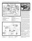
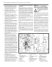
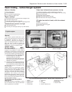
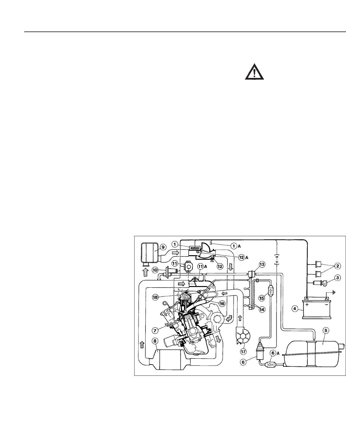
Fig. 13.48 Bosch L3.1 Jetronic fuel injection system - 1372 cc Turbo ie engine (Sec 9E)
1 ECU
1A Diagnostic socket
2 Injection system relay and
fuel pump relay
3 Ignition switch
4 Battery
5 Fuel tank
6 Fuel pump
6A Primary fuel filter
7 Coolant temperature
sensor
8 Intake air cooling radiator
(intercooler)
9 Air cleaner
10 Supplementary air valve
11 Throttle position switch
11A Throttle housing
12 Airflow meter
12A Intake air temperature
sensor
13 Fuel pressure regulator
14 Fuel rail (to injectors)
15 Secondary fuel filter
16 Injectors
17 Injector cooling fan
18 Thermostatic switch (to
engage injector cooling fan)