


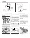
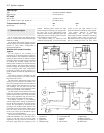

outwards, they rotate the cam relative to the
distributor shaft, and so advance the spark.
The weights are held in position by two
springs and it is the tension of the springs
which is largely responsible for correct spark
advancement.
The vacuum advance is controlled by a
diaphragm capsule connected to the
carburettor venturi. The vacuum pressure
varies according to the throttle valve plate
opening and so adjusts the ignition advance
in accordance with the engine requirements.
Digiplex ignition system
This electronic system eliminates the
mechanical contact breaker and centrifugal
advance mechanism of conventional
distributors and uses an electronic control
unit to provide advance values according to
engine speed and load. No provision is made
for adjustment of the ignition timing.
Information relayed to the control unit is
provided by two magnetic sensors which
monitor engine speed and TDC directly from
the engine crankshaft.
A vacuum sensor in the control unit
converts intake manifold vacuum into an
electric signal.
The control unit selects the optimum
advance angle required and a closed
magnetic circuit resin coil guarantees a spark
owing to the low primary winding resistance.
Five hundred and twelve advance values
are stored in the control unit memory to suit
any combination of engine operating
conditions.
No maintenance is required to the
distributor used on this system.
Distributor drive
The mechanical breaker type distributor on
903 cc engines and the Digiplex type
distributor on 903 cc ES engines are mounted
on the cylinder head and driven from a gear
on the camshaft through a shaft which also
drives the oil pump.
The distributor on 1116 cc and 1301 cc
engines is mounted on the crankcase and is
driven from a gear on the auxiliary shaft as is
also the oil pump.
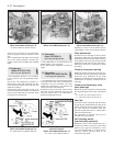
2 Mechanical contact breaker
- points servicing
3
1 At the intervals specified in “Routine
Maintenance”, prise down the clips on the
distributor cap and place the cap with high
tension leads to one side.
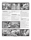
2 Pull off the rotor.
3 Remove the spark shield. Mechanical wear
of the contact breaker reduces the gap.
Electrical wear builds up a “pip” of burned
metal on one of the contacts. This
|prevents the gap being measured for
re-adjustment, and also spoils the electric
circuit.
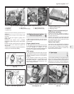
Ducellier type distributor
4 To remove the contact breaker movable
arm, extract the clip and take off the washer
from the top of the pivot post.
5 Extract the screw and remove the fixed
contact arm.
6 Clean the points by rubbing the surfaces on
a fine abrasive such as an oil stone. The point
surface should be shaped to a gentle convex
curve. All the “pip” burned onto one contact
must be removed. It is not necessary to go on
until all traces of the crater have been
removed from the other. There is enough
metal on the contacts to allow this to be done
once. At alternate services, fit new points.
Wash debris off cleaned points and
preservatives off new ones.
7 Now the distributor should be lubricated.
This lubrication is important for the correct
mechanical function of the distributor, but
excess lubrication will ruin the electrical
circuits, and give difficult starting.
8 Whilst the contact breaker is off, squirt
some engine oil into the bottom part of the
distributor, onto the centrifugal advance
mechanism below the plate.
9 Wet with oil the felt pad on the top of the
distributor spindle, normally covered by the
rotor arm.
10 Put just a drip of oil on the pivot for the
moving contact.
11 Smear a little general purpose grease
onto the cam, and the heel of the moving
contact breaker.
12 Refit the contact points and then set the
gap in the following way.
13 Turn the crankshaft by applying a spanner
to the pulley nut or by jacking up a front
wheel, engaging top gear and turning the
roadwheel in the forward direction of
travel. Keep turning until the plastic
heel of the movable contact arm is on the
high point of a cam lobe on the distributor
shaft.
14 Set the points gap by moving the fixed
contact arm until the specified feeler blades
are a sliding fit. Tighten the fixed contact arm
screw.
15 Check the contact end of the rotor arm.
Remove any slightly burnt deposits using fine
abrasive paper. Severe erosion will
necessitate renewal of the rotor.
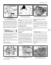
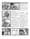
16 Wipe out the distributor cap and check for
cracks or eroded contacts (photo). Renew if
evident or if the carbon brush is worn.
17 Refit the spark shield, rotor and distributor
cap.
18 Setting the contact breaker gap with a
feeler blade must be regarded as a means of
ensuring that the engine will start. For
optimum engine performance, the dwell angle
must be checked and adjusted as described
in Section 3.
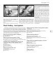
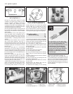
Marelli type distributor
19 Open the points with a finger nail and
inspect their condition. If they are badly
eroded or burned, then they must be
renewed. The contact points can only be
renewed complete with carrier plate as an
assembly.
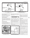
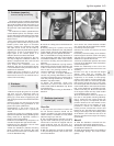
20 Release the low tension leads from the
terminals on the distributor body (photo).
21 Extract the screws which hold the vacuum
advance capsule to the distributor body. Tilt
the capsule and release its link rod from the
contact breaker carrier plate (photo).
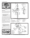
22 Prise out the E-clip from the breaker
carrier and then withdraw the contact
assembly from the top of the distributor shaft.
Ignition system 4•3
2.21 Extracting vacuum diaphragm unit
screw
2.20 Marelli distributor2.16 Interior of distributor cap showing
carbon brush
4