


E-126
Principles of Measurement
Illuminating/Viewing System
This instrument utilizes the di:8°/de:8° geometry conforming to CIE No. 15, ASTM E1164, DIN 5033
Teil 7, ISO 7724/1, and JIS Z8722-1982 (diffused illumination, 8-degree viewing angle) standards, and
offers measurement with automatic SCI (specular component included) and SCE (specular component
excluded) switching.
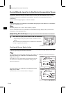
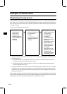
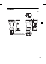
The flow of measurement is shown below.
1 Light from the xenon lamps diffuses on the inner surface of the integrating sphere and illuminates the
specimen uniformly.
2 a: The light reflected from the specimen surface at an angle of 8° to the normal of the surface is
received by the specimen-measuring optical system.
b: The light diffused in the integrating sphere is received by the illumination-monitoring optical
system and guided to the sensor.
3 The light reflected from the specimen surface and the diffused light are divided into each wavelength
component by the specimen-measuring optical system and illumination-monitoring optical sensor
respectively, and then signals proportional to the light intensity of each component are output to the
analog processing circuit.
By processing the outputs from the specimen-measuring optical system and the illumination-monitoring
sensor with the calculation by the CPU, the instrument compensates for slight fluctuations in the spectral
characteristics and intensity of the illumination light. (Double-beam system)
1 Illumination
Light from the
xenon lamps
diffuses in the
integrating sphere
and illuminates the
specimen
uniformly.
2 Receiving
a:Light reflected from
the specimen is
received.
b:Light diffused in the
integrating sphere is
received.
3 Sensing
Light is transmitted to
the specimen-
measuring and
illumination
monitoring optical
systems, where the
light in the
wavelength range of
400 to 700 nm is
divided into 10 nm-
pitch components,
and signals
proportional to the
light intensity of each
component are
output to the analog
processing circuit.