


ENGINE TOP END 4-19
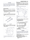
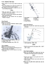
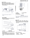
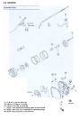
Valve Lapping
::70
l'
"-'
-r-~
-""~ccccc..iccc.-c ~~
@
@,
3. Valve
1 .Lapper
2. Valve Seat
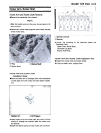
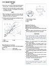
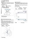
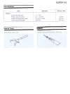
Measure Valve-to-Guide Clearance
(Wobble Method)
If a small bore gauge is not available, inspect the valve
guide wear by measuring the valve to valve guide
clearance with the wobble method as indicated below.
.Insert a new valve into the guide and set a dial gauge
against the stem perpendicular to it as close as possible
to the cylinder head mating surface-
.Move the stem back and forth to measure valve/valve
guide clearance.
.Repeat the measurement in a direction at a right angle
to the first.
*If the reading exceeds the service limit, replace the
guide.
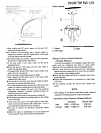
NOTE
0 The reading is not actual valve/valve guide clearance
because the measuring point is above the guide.
Valve/Valve Guide Clearance (Wobble Method)
Standard Service Limit
Inlet 0.031 -0.140 mm 0.34 mm
Exhaust 0.085 -0.180 mm 0.41 mm
OAfter making the 32° grind, return to the seat O.D.
measurement step above.
.To measure the seat width, use a vernier caliper to
measure the width of the 45° angle portion of the seat
at several places around the seat.
*If the seat width is too narrow, repeat the 45° grind until
the seat O.D. measurement step above.
* If the seat width is too wide, make the 60° grind
described below.
.Grind the seat at a 60° angle until the seat width is
within the specified range.
OTo make the 60° grind, fit 60° cutter into the holder, and
slide it into the valve guide.
OTurn the holder, while pressing down lightly.
O After making the 60° grind, return to the seat width
measurement step above.
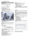
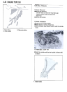
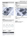
.Lap the valve to the seat, once the seat width and O.D.
are within the ranges specified above.
O Put a little coarse grinding compound on the face of the
valve in a number of places around the valve head.
O Spin the valve against the seat until the grinding
compound produces a smooth, matched surface on
both the seat and the valve.
0 Repeat the process with a fine grinding compound.
.The seating area should be marked about in the middle
of the valve face.
*If the seat area is not in the right place on the valve,
check to be sure the valve is the correct part. If it is, it
may have been refaced too much; replace it.
.Be sure to remove all grinding compound before
assembly.
.When the engine is assembled, be sure to adjust the
valve clearance (see Valve Clearance Adjustment).