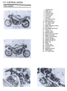
ELECTRICAL SYSTEM 15-15
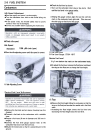
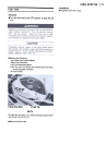
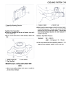
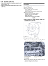
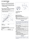
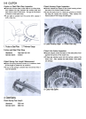
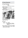
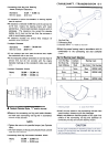
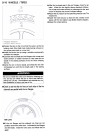
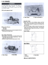
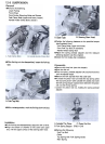
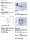
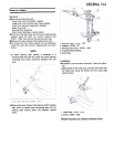
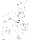
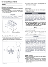
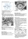
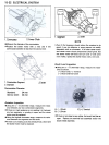
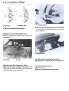
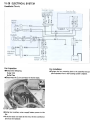
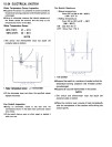
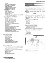
.Connect the brown lead terminal to the other battery
( + ) terminal and connect the black/yellow lead terminal
to the battery ( -) terminal momentarily. At this time the
bulb should not be lit.
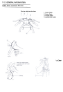
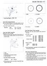
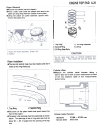
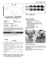
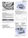
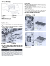
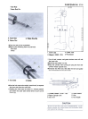
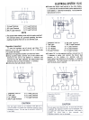
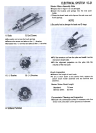
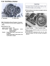
4. Y1 Lead Terminal
5. Y2 Lead Terminal
6. Y3 Lead Terminal
1. W Lead Terminal
2. BR Lead Terminal
3. BK/Y Lead Terminal
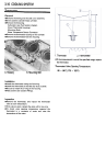
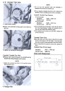
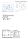
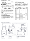
NOTE
0 The actual meter reading varies with the meter used and
the individual diode, but, generally speaking, the lower
reading should be from zero to one half the scale.
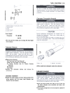
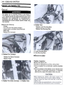
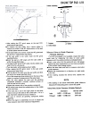
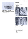
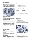
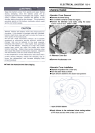
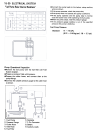
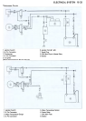
6. BR Lead Terminal
7. BK/Y Lead Terminal
8. Y1 Lead Terminal
9. Y2 Lead Terminal
10. Y3 Lead Terminal
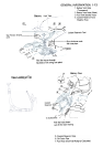
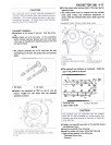
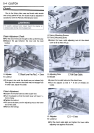
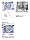
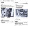
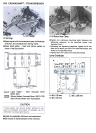
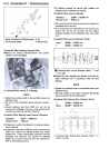
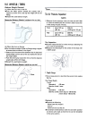
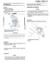
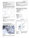
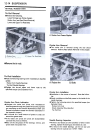
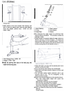
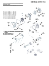
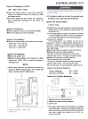
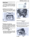
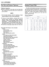
1. Regulator/Rectifier
2. Test Light
3. 1 2 V Battery
4. 12 V Battery
5. W Lead Terminal
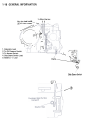
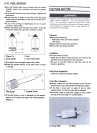
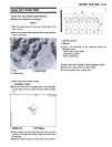
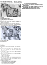
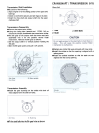
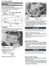
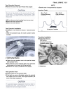
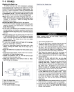
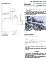
.To apply 24 V to the regulator/rectifier, connect two 12
V batteries in series, and connect the brown lead
terminal to the battery ( + ) terminal and the
black/yellow lead terminal to the battery ( -) terminal
momentarily. The bulb should now light and stay on
until the bulb circuit is opened.
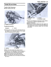
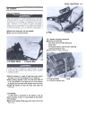
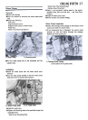
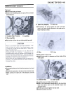
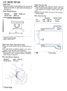
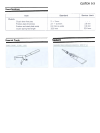
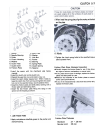
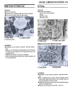
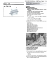
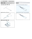
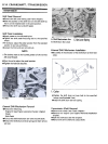
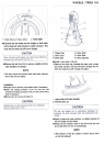
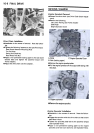
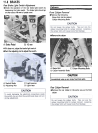
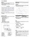
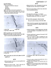
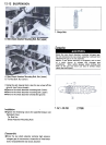
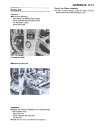
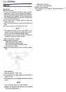
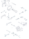
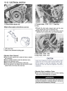
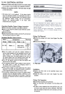
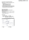
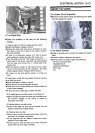
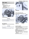
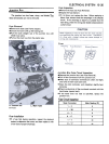
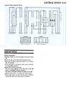
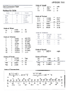
Regulator Inspection
To test the regulator out of circuit, use three 12 V
batteries and a test light made from 12 V 3 -6 W bulb
in a socket with leads.
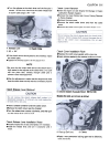
.Remove the regulator/rectifier unit from the frame.
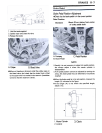
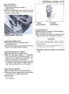
.Using auxiliary leads, connect one of the yellow lead
terminal at the unit to the battery ( + ) terminal, and
connect the test light between the black/yellow lead
terminal at the unit. and the battery ( -) terminal.
.At this time the bulb should not be lit.
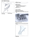
5. Y, Lead Terminal
6. Y2 Lead Terminal
7. Y3 Lead Terminal
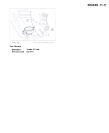
1. Regulator/Rectifier
2. Test Light
3. 12 V Battery
4. BK/Y Lead Terminal