


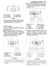

15-14 ELECTRICAL SYSTEM
57001-983)
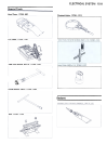
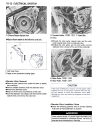
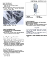
Connect the hand tester (special tool:
as shown in table.
Note the readings (total 3 measurement)
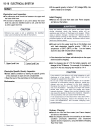
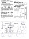
Rectifier Inspection
.Check the rectifier resistance as follows.
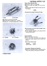
.Remove the regulator/rectifier and disconnect the
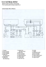
connector 2 (see Charging System Wiring Diagram).
.Connect an ohmmeter to the regulator/rectifier as
shown in the Table, and check the resistance in both
directions of each diode following the table.
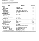
Stator Coil Resistance
Meter
Range
Connections
Reading
Meter ( + ) to
One yellow
lead
(Connector 1 )
Meter (-) to
Rectifier Circuit Inspection
0.2 -
0.90
Another
yellow lead
(Connector 1 )
x1O
Connections
Meter
Range
No.
Meter ( + ) to I Meter ( -) to I Reading
1
YI
2
3
4
Y2
Y3
Y1
w
00
5
6
x10o.
Y2
Y3
BK/Y
1 /2 scale
or
x 100 n
Y1
Y2
Y3
Y1
w
*If there is more resistance than shown in the Table, or
no meter reading (infinity) for any two leads, the stator
has an open lead and must be replace. Much less than
this resistance means the stator is shorted, and must be
replaced-
.Using the highest resistance range of the hand tester
measure the resistance between each of the yellow
leads and chassis ground.
* Any meter reading less than infinity ( 00 ) indicates a
short, necessitating stator replacement.
* If the stator coils have normal resistance, but the voltage
check showed the alternator to be defective; then the
rotor magnetism have probably weakened, and the rotor
must be replaced.
7
8
9
10
BK/Y
11
12
Y2
Y3
00