


10-6 FI NAl DRIVE
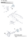
Sprocket, Coupling
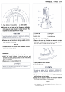
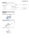
Engine Sprocket Removal
.Loosen the drive chain (see Drive Chain Slack Adjust-
ment) .
.Remove the following.
Left Lower Fairing (see Frame chapter)
Shift Pedal
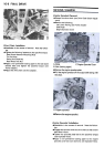
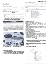
Engine Sprocket Cover
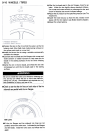
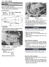
C. Engine Sprocket Cover
A. Bolts
B. Bolt (locking agent)
Drive Chain Installation
.Installation is the reverse of removal. Note the follow-
ing.
.Tighten the following fasteners to the specified torque.
Rear Shock Absorber Mounting Nuts
Tie-Rod Nuts
Swing Arm Shaft Nut
Rear Wheel Axle Nut
.Applya non-permanent locking agent to the side stand
bracket bolts and tighten the specified torque (see
Frame chapter) .
.Adjust the drive chain (see this chapter).
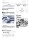
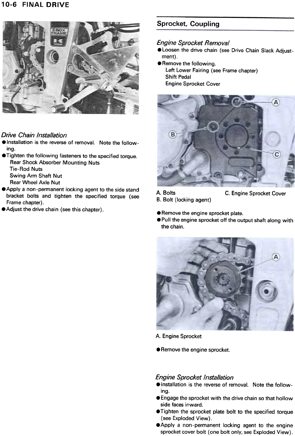
.Remove the engine sprocket plate.
.Pull the engine sprocket off the output shaft along with
the chain.
A. Engine Sprocket
.Remove the engine sprocket.
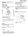
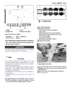
Engine Sprocket Installation
.Installation is the reverse of removal. Note the follow-
ing.
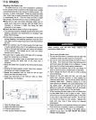
.Engage the sprocket with the drive chain so that hollow
side faces inward.
.Tighten the sprocket plate bolt to the specified torque
(see Exploded View).
.Apply a non-permanent locking agent to the engine
sprocket cover bolt (one bolt only, see Exploded View).