


ELECTRICAL SYSTEM 15-13
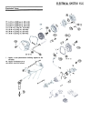
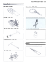
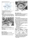
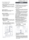
Alternator Rotor Cleaning Area
A. Holding Plate
B. Grommets
c. Mounting Bolts
D. Stator
1. The tapered portion of the crankshaft.
2. The alternator rotor bolt and the threads in the
crankshaft.
3. The tapered portion of the alternator rotor.
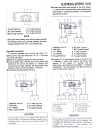
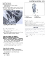
4. Chamfer Stator Installation Notes
.Fit the stator coil lead grommet first, and the pickup coil
lead grommet into the notch of cover securely-
.Route the stator coil leads in accordance with the Wire
Routing in the General Information chapter.
.Install the washer so that the chamfer side faces out.
.Tighten the alternator rotor bolt to the specified torque
(see Exploded View) while holding the alternator rotor
steady with the flywheel holder (special tool:
57001-1313).
A. Silicone Sealant Applied Areas
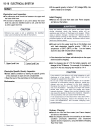
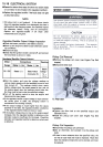
Alternator Inspection
There are three types of alternator failures: short, open
(wire burned out), or loss in rotor magnetism. A short or
open in one of the coil wires will result in either a low
output, or no output at all. A loss in rotor magnetism,
which may be caused by dropping or hitting the alternator,
by leaving it near an electromagnetic field, or just by aging,
will result in low output.
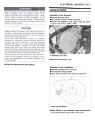
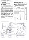
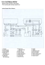
.To check the alternator output voltage, do the following
procedures. Refer to the appropriate chapters and
charging system Wiring Diagram.
Turn off the ignition switch.
Disconnect connector 1.
Connect the hand tester (special tool: 57001-983)
as shown in table.
Start the engine.
Run it at the rpm given in table.
Note the voltage readings (total 3 measurements).
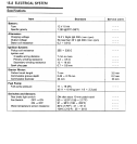
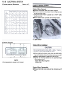
Alternator Output Voltage
.Install a new gasket and the alternator cover.
.Tighten the cover bolts to the specified torque (see
Exploded View).
.Fill the engine with engine oil (see Engine Lubrication
System chapter).
Meter
Range
Connections
Meter (+) to
Meter (-) to
250 V
AC
Another
yellow lead
(Connector 1 )
Reading
4000
rpm
about
43V
One yellow
lead
(Connector 1)
*If the output voltage shows the value in table, the
alternator operators properly and the regulator/rectifier
is damaged. A much lower reading than that given in
the table indicates that the alternator is defective.
.Check the stator coil resistance as follows:
Stop the engine.
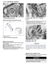
Stator Coil Removal
.Remove the alternator cover (see this chapter).
.Remove the holding plate.
.Unit the pickup coil lead and stator coil lead grommets
out of the notch of cover.
.Unscrew the mounting bolt. and take off the stator.