


2 - NAV PAGES
34
190-00357-00 Rev E
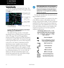
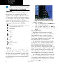
NOTE: If the 500W-series unit is unable to determine
a GPS position, the present position (airplane) symbol
will appear on the Map Page in yellow. No symbol will
be present when there is no active flight plan.
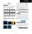
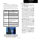
Map Symbols
Varioussymbols are used to distinguish between
waypoint types. The identifiers for any on-screen
waypoints can also be displayed. (By default the identi-
fiers are enabled.) Special-use and controlled airspace
boundaries appear on the map, showing the individual
sectorsinthecaseofClassB,ClassC,orClassD
airspace. The following symbols are used to depict the
various airports and navaids on the Map Page:
Airport with hard surface runway(s); Primary runway shown
Airport with soft surface runway(s) only
Private Airfield
Intersection
VOR
VORTAC
VOR/DME
TACAN
DME
NDB
Localizer
Locator Outer Marker
Heliport
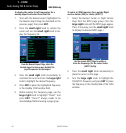
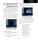
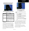
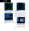
Map Range
The map display can be set to 23 different range
settings from 500 feet to 2000 nautical miles (statute
and metric units are also available). The range is indi-
cated in the lower left-hand corner of the map display,
and represents the top-to-bottom distance covered by
the map display.
The map range appears in the lower left corner.
Use the RNG key to select the desired map range.
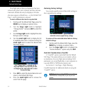
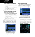
To select a map range:
1. Press the up arrow side of the RNG key to
zoom out to a larger map area.
2. Press the down arrow side of the RNG key
to zoom in to a smaller map area and more
detail.
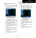
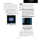
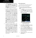
Map Page Auto Zoom
An autozoom feature is available which auto-
matically adjusts from an en route range of 200 NM
through each lower range, stopping at a range of
1.0 NM as you approach your destination waypoint.
The autozoom feature is turned on/off from the map
setup page described later in this section.
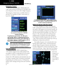
The Map Page also displays a background map
showing lakes, rivers, coastlines, highways, railways
and towns. When a map scale is selected below the
lower limit at which the map detail was originally
created, an “overzoom” indication appears on the map
display, below the scale reading. “Overzoom” indicates
that the detail at this scale may not accurately repre-
sent actual conditions (and extra caution should be
observed when these scales are used for navigation).
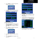
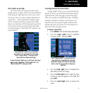
The “Setup Map?” option allows you to define the
maximum scale at which each map feature appears.
This provides you with complete control to minimize
screen clutter. You can also quickly remove items from
the map using the CLR key.
Map Page