


ENGINE
3.31
Piston Ring-to-Groove Clearance
Top Ring Std: .0016-.0031I (.040-.080 mm)
Limit: .0059I (15 mm)
Second Ring Std: .0012-.0028I (.030-.070 mm)
Limit: .0059I (15 mm)
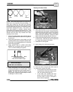
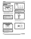
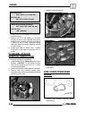
4. Measure piston ring to groove clearance by
placing the ring in the ring land and measuring
with a thickness gauge. Replace piston and rings
if ring-to-groove clearance exceeds service
limits.
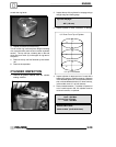
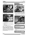
PISTON RING INSTALLED
GAP
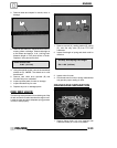
1. Place each piston ring inside cylinder usingpiston
to push ring squarely into place as shown at right.
25-50mm
Cylinder
Piston Ring
Feeler Gauge
Piston Ring Installed Gap
Top Ring
Std: .0079-.0138I (.20-.36 mm)
Limit: .039I (1.0 mm)
Second Ring
Std: .0079-.0138I (.20-.36 mm)
Limit: .039I (1.0 mm)
Oil Ring
Std: .0079-.0276I (.20-.70 mm)
Limit: .059I (1.5 mm)
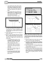
2. Measure installed gap with a feeler gauge at both
the top and bottom of the cylinder. NOTE: A
difference in end gap indicates cylinder taper.
The cylinder should be measured for excessive
taper and out of round.
3. If the bottom installed gap measurement exceeds
the service limit, replace the rings. If ring gap is
below specified limit, file ring ends until gap is
within specified range.
NOTE: Always check piston ring installed gap after
re-boring a cylinder or when installing new rings. A
re-bored cylinder should always be scrubbed
thoroughly with hot soapy water, rinsed, and dried
completely. Wipe cylinder bore with an oil rag
immediately to remove residue and prevent rust.
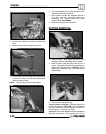
CRANKCASE DISASSEMBLY
NOTE: The recoil starter, starter motor, starter drive,
flywheel, stator, cam chain and sprockets can be
serviced with the engine in the frame.
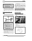
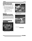
STARTER DRIVE
REMOV
AL/INSPECTION
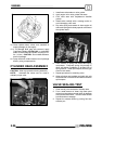
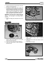
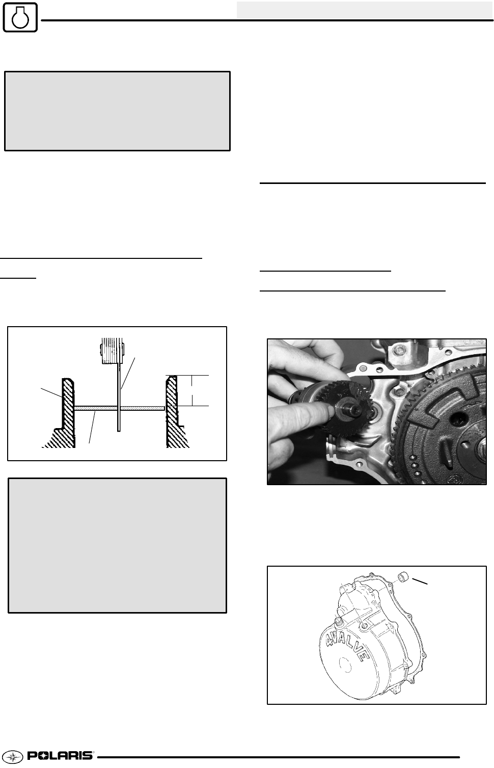
1. Remove recoil housing bolts and remove
housing.
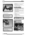
2. Remove starter drive assembly. Note the thrust
washer located at the rear of the drive
mechanism.
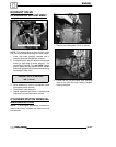
3. Inspect the thrust washer for wear or damage and
replace if necessary.
A