ENGINE
3.5
ENGINE FASTENER TORQUE
PA
TTERNS
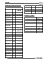
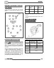
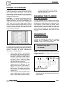
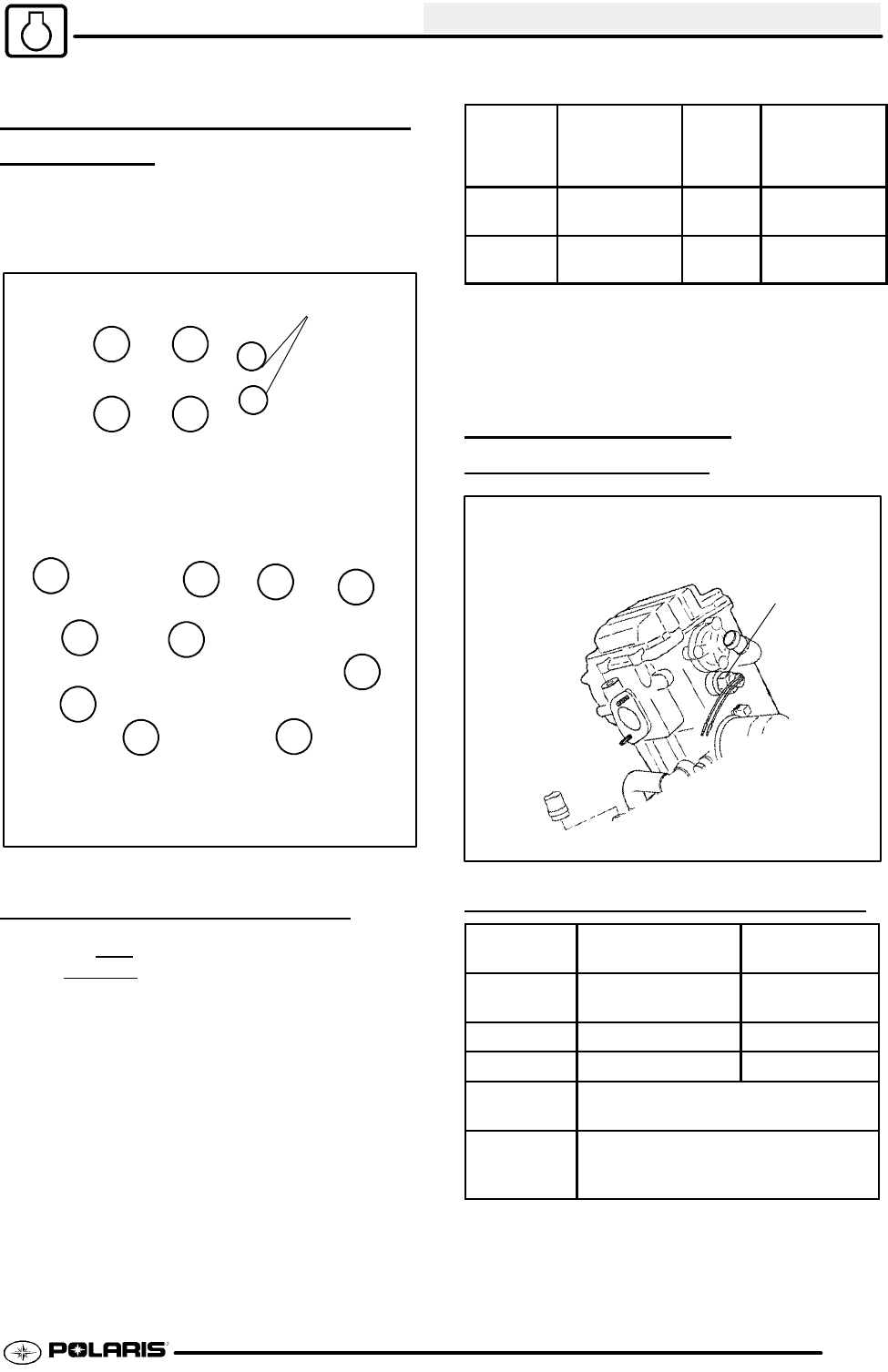
Tighten cylinder head, cylinder base, and crankcase
fasteners in 3 steps following the sequence outlined
below.
6mm
1
23
4
6
5
Cylinder Head
Cylinder Base
Pattern
Crankcase
Pattern
1
2
3
4
9
7
6
8
5
10
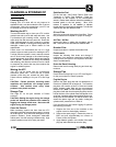
PISTON IDENTIFICATION
The piston may have an identification mark or the
piston may not
have an identification mark for
piston placement. If the piston has an identification
mark, follow the directions for piston placement
below. If the piston does not have an identification
mark, the direction for placement of the piston does
not matter.
Note the directional and identification marks when
viewing the pistons from the top. The letter “F”, “ !
”, “ "”or: must always be toward the flywheel side
of the engine. The other numbers are used for
identification as to diameter, length and design. Four
stroke engine rings are rectangular profile. See text
for oil control ring upper rail installation. Use the
information below to identify pistons and rings.
Engine
Model
No.
Oversize
Available*
(mm)
Piston
Length
Standard
Piston Iden-
tification
EH50PLE .25
.50
72 mm C
EH42PLE 25
.50
66 mm B
*Pistons and rings marked 25 equal .25mm (.010I)
oversized
Pistons and rings marked 50 equal .50mm (.020I)
oversized
COOLING SYSTEM
SPECIFICA
TIONS
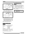
Thermistor
26 ± 2.1 ft.lbs.
(35 ± 3Nm)
THERMISTOR READING DURING OPERA
TION
Condition
Approx. Reading
(Min--Max)
Temperature
Hot Light
On
178Ω -- 190Ω 215° F
(102° C)
Fan Off 296Ω -- 316Ω 180° F(82° C)
Fan On 236Ω -- 251Ω 195° F(91° C)
System
Capacity
2.25 Quarts
(2.13L)
Radiator
Cap Relief
Pressure
13 PSI


