


ENGINE
3.18
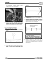
A
B
C
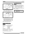
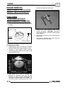
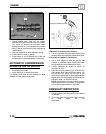
1. Check release lever shaft (A) for smooth
operation throughout the entire range of rotation.
The spring (B) should hold the shaft weight
against the stop pin. In this position, the actuator
ball (C) will be held outward in the compression
release mode.
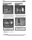
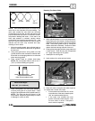
2. Remove release lever shaft and return spring.
3. Inspect shaft for wear or galling.
4. Inspect lobe on end of release lever shaft and
actuator ball for wear and replace if necessary.
AUTOMATIC COMPRESSION
RELEASE INSTALLA
TION
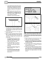
1. Slide spring onto shaft.
2. Apply engine oil to release lever shaft.
The actuator ball must be held outward to allow
installation of the release lever shaft.
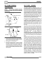
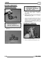
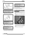
Spring in relaxed position
Stop pin
If Camshaft Is Removed From Engine:
3. Turn the camshaft until the actuator ball is in the
lowest position and install the release lever shaft.
If Camshaft Is Installed In The Engine:
4. Use a small magnet to draw the actuator ball
outward, or rotate the engine until the cam lobes
face upward and install release lever shaft.
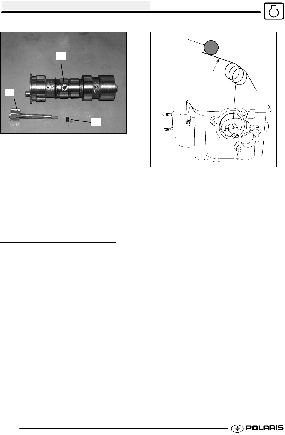
5. Position camshaft as shown at bottom of
illustration at right.
6. Place arm of spring under stop pin as shown and
push release lever inward until fully seated. Do
not pre-wind the spring one full turn or the
compression release will not disengage when the
engine starts. Check operation of mechanism as
outlined in Step 1 of Removal (above).
NOTE: When shaft is properly installed, actuator
ball will be held in the “out” position. It isimportant
to note that spring pressure is very light.
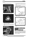
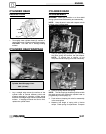
CAMSHAFT INSPECTION
1. Visually inspect each cam lobe for wear, chafing
or damage.
2. Thoroughly clean the cam shaft, making sure the
oil feed holes are not
obstructed.