


MAINTENANCE
2.27
CAUTION: Failure to position the crankshaft at TDC
on compression stroke will result in improper valve
adjustment.
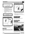
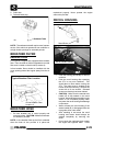
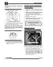
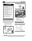
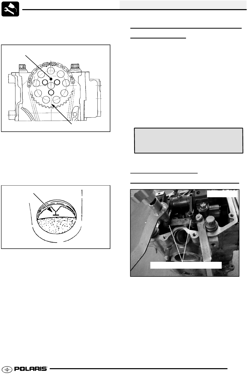
Sprocket alignment pin facing up
Crankshaft-to-Camshaft Centerline
6. Rotate engine slowly with recoil rope, watching
the intake valve(s) open and close.
NOTE: At this point watch the camshaft sprocket
locating pin and slowly rotate engine until locating pin
is facing upward, directly in line with the crankshaft to
camshaft center line as shown. The camshaft lobes
should be pointing downward.
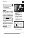
7. Verify accurate TDC positioning by observing the
“T” mark aligned with the pointer in the timing
inspection hole. In this position there should be
clearance on all valves.
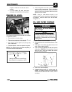
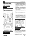
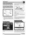
INTAKE VALVE CLEARANCE
ADJUSTMENT
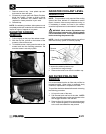
1. Insert a .006″ (.15mm) feeler gauge between end
of intake valve stem and clearance adjuster
screw.
2. Using a 10 mm wrench and a screwdriver, loosen
adjuster lock nut and turn adjusting screw until
there is a slight drag on the feeler gauge.
3. Hold adjuster screw and tighten adjuster lock nut
securely.
4. Re-check the valve clearance.
5. Repeat adjustment procedure if necessary until
clearance is correct with locknut secured.
6. Repeat this step for the other intake valve.
.006″ (.15 mm)
INTAKE VALVE CLEARANCE
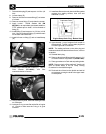
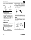
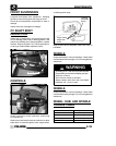
EXHAUST VALVE
CLEARANCE
ADJUSTMENT
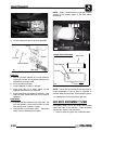
Feeler Gauge for Both Valves
500 Engine
NOTE: The exhaust valves share a common rocker
arm, and must be adjusted using two feeler gauges.
1. Insert .006 feeler gauge(s) between end of
exhaust valve stem and adjuster screw(s).
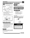
2. Loosen locknut(s) and turn adjuster screw(s) until
there is a slight drag on feeler gauge(s). The
Valve/Clutch Adjuster Tool (PA--44689) can be
used to adjust the engines valves. NOTE: Both
feeler gauges should remain inserted during
adjustment of each valve.