


BRAKES
9.9
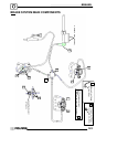
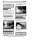
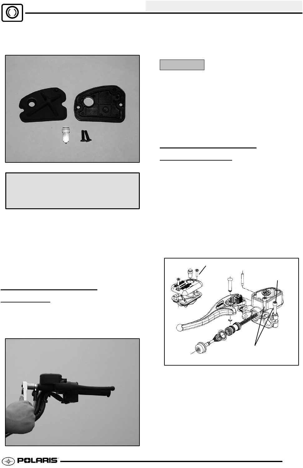
13. Install diaphragm, cover and screws. Tighten
screws to specification 5 in. lbs. (0.56 Nm).
Reservoir Cover Torque -
5 in. lbs. (.56 Nm)
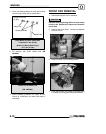
14. Field test machine at low speed before putting
into service. Check for proper braking action and
lever reserve. With lever firmly applied, lever
reserve should be no less than 1/2″ (1.3 cm) from
handlebar.
15. Check brake system for fluid leaks and inspect all
hoses and lines for wear or abrasion. Replace
hose if wear or abrasion is found.
MASTER CYLINDER
REMOV
AL
1. Clean master cylinder and reservoir assembly.
Make sure you have a clean work area to
disassemble brake components.
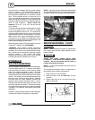
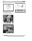
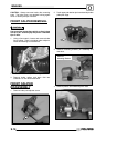
2. Place a shop towel under brake line connection at
master cylinder. Loosen banjo bolt; remove bolt
and sealing washers.
CAUTION:
Brake fluid will damage finished surfaces. Do not
allow brake fluid to come in contact with finished
surfaces.
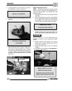
3. Remove master cylinder from handlebars.
4. Hold brake upright and continue to remove
master cylinder. Cover brake line to avoid
spillage.
MASTER CYLINDER
INSTALLA
TION
Notice: When replacing the brake master cylinder
assembly or master cylinder parts, use the correct
parts. There are different brake master cylinders for
the different Polaris ATV models. Refer to your parts
manual or guide for the correct parts. This master
cylinder is not serviceable and is replaced as a
unit.
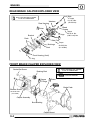
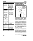
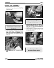
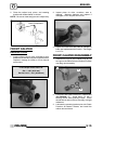
1. Install master cylinder on handlebars. Torque
mounting bolts to 25 in. lbs. (3 Nm). Torque the
inside bolt first asindicated in the illustration tothe
right.
Torque both bolts to
25 in.lbs. (3 Nm)
Torque this
bolt first
5in.lbs.
(.56 Nm)
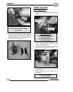
NOTE: To speed up the brake bleeding procedure,
the master cylinder can be purged of air before brake
line is attached. Fill with DOT3 Brake Fluid (PN
2870990) and pump lever slowly two to three times
with finger over the outlet end to purge master cylinder
of air.