


CLUTCHING
6.2
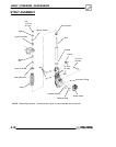
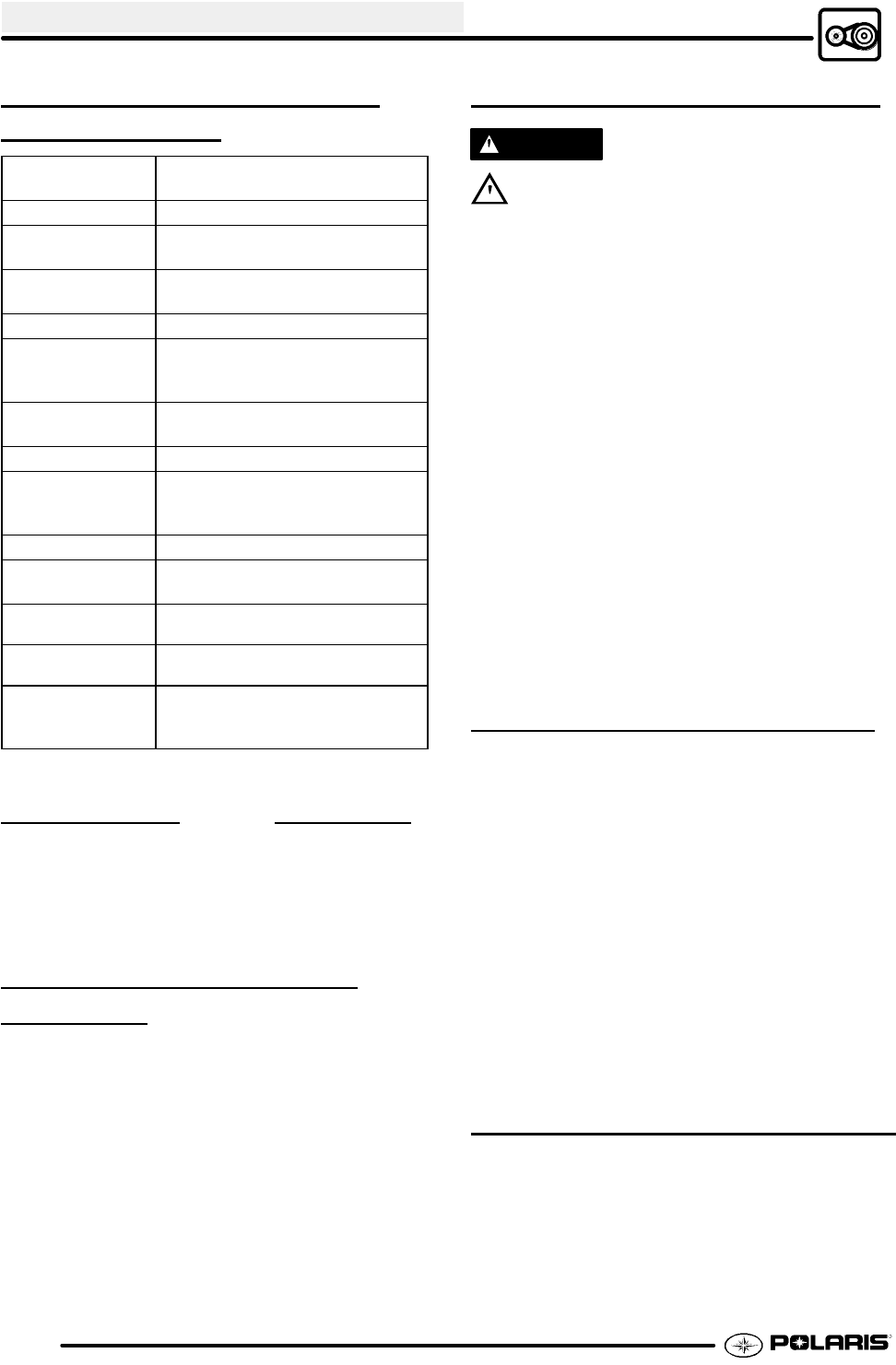
SPECIAL SERVICE TOOLS
AND
SUPPLIES
TOOL
DESCRIPTION
PART NUMBER
Clutch Puller 2870506
Clutch Holding
Wrench
9314177
Clutch Holding
Fixture
2871358
Spider Nut Socket 2870338
Drive Clutch
Spider Removal
and Install Tool
2870341
Driven Clutch
Puller
2870913
Roller Pin Tool 2870910
Clutch Bushing
Replacement Tool
Kit
2871226
Piston Pin Puller 2870386
EBS Clutch
Alignment Tool
2872292
EBS Bushing
Replacement Kit
2201379
Clutch
Compression Tool
8700220
Clutch Bushing
Replacement Tool
Kit
2871025
SPECIAL SUPPLIES PART NUMBER
Loctitet 680 2870584....................
RTV Silicone Sealer 2870661.............
Loctite Gasket Remover 2870601..........
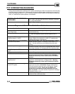
PVT SYSTEM FASTENER
T
ORQUES
Drive Clutch Retaining Bolt 40 ft. lbs. (54 Nm)...
Driven Clutch Retaining Bolt 17 ft. lbs. (23 Nm)..
PVT Inner Cover Bolts 12 ft. lbs. (16 Nm).......
Drive Clutch Spider EBS Clutch 200 ft. lbs.......
(271 Nm)...................................
Drive Clutch Spider Lock Nut (Plastic) 15 ft. lbs...
(20.3 Nm)...................................
Drive Clutch Cover Plate 90 in. lbs. (10 Nm).....
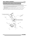
PVT OPERATION OVERVIEW
WARNING
All PVT maintenance or repairs should be
performed only by a certified Polaris Master Service
Dealer (MSD) technician who has received theproper
training and understands the procedures outlined in
this manual. Because of the critical nature and
precision balance incorporated into the PVT
components, it is absolutely essential that no
disassembly or repair be made without factory
authorized special tools and service procedures.
The Polaris Variable Transmission (PVT) consists of
three major assemblies: 1) The Drive Clutch; 2) The
Driven Clutch; and 3) The Drive Belt. The internal
components of the drive clutch and driven clutch
control engagement (initial vehicle movement), clutch
upshift and backshift. During the development of a
Polaris ATV, the PVT system is matched first to the
engine power curve; then to average riding conditions
and the vehicle’s intended usage. Therefore,
modifications or variations of components at random
are never recommended. Proper clutch setup and
careful inspection of existing components must be the
primary objective when troubleshooting and tuning.
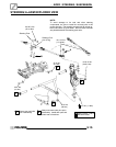
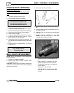
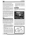
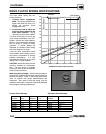
DRIVE CLUTCH OPERATION
Drive clutches primarily sense engine RPM. The two
major components which control its shifting function
are the shift weights and the coil spring. Whenever
engine RPM is increased, centrifugal force is created,
causing the shift weights to push against rollers onthe
moveable sheave, which is held open by coil spring
preload. When this force becomes higher than the
preload in the spring, the outer sheave moves inward
and contacts the drive belt. This motion pinches the
drive belt between the spinning sheaves and causes
it to rotate, which in turn rotates the driven clutch.
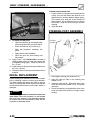
At lower RPM, the drive belt rotates low in the drive
clutch sheaves. As engine RPM increases,
centrifugal force causes the drive belt to be forced
upward on drive clutch sheaves.
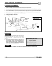
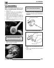
DRIVEN CLUTCH OPERATION
Driven clutches primarily sense torque, opening and
closing according to the forces applied to it from the
drive belt and the transmission input shaft. If the
torque resistance at the transmission input shaft is
greater than the load from the drive belt, the drive belt
is kept at the outer diameter of the driven clutch
sheaves.