MAINTENANCE
2.16
THROTTLE CABLE /
ELECTRONIC
THROTTLE
CONTROL (ETC
SWITCH)
ADJUSTMENT
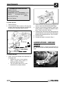
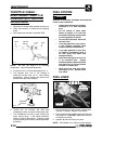
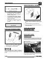
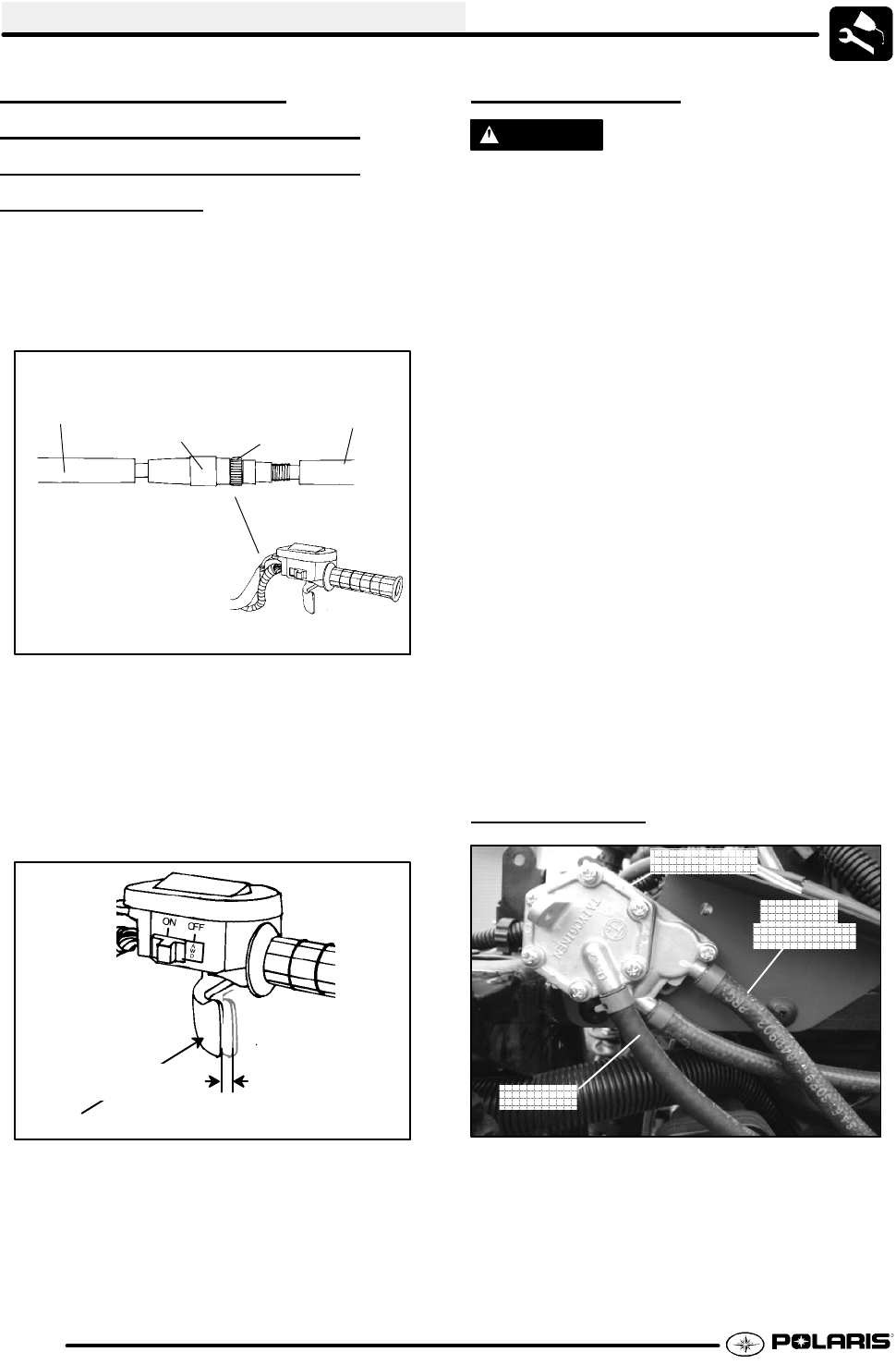
1. Slide boot off throttle cable adjuster and jam nut.
2. Place shift selector in neutral and set parking
brake.
3. Start engine and set idle to specified RPM.
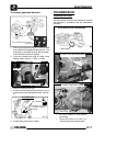
Boot
Adjuster
Sleeve
Lock-
nut
Boot
Ill. 1
NOTE: Be sure the engine is at operating
temperature. See Idle Speed Adjustment.
4. Loosen lock nut on in-line cable adjuster (Ill. 1).
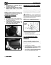
5. Turn adjuster until 1/16″ to 1/8″ freeplay is
achieved at thumb lever. (Ill. 2). After making
adjustments, quickly actuate the thumb lever
several times and verify freeplay.
1/16″ -1/8″
Freeplay
Direction
of travel
Ill. 2
6. Tighten lock nut securely and slide boot
completely in place to ensure a water-tight seal.
7. Turn handlebars from left to right through the
entire turning range. If idle speed increases,
check for proper cable routing. If cable is routed
properly andin good condition, repeat adjustment
procedure.
FUEL SYSTEM
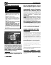
WARNING
Gasoline is extremely flammable and explosive
under certain conditions.
S Always stop the engine and refuel
outdoors or in a well ventilated
area.
S Do not smoke or allow open
flames or sparks in or near the
area where refueling is performed
orwheregasolineisstored.
S Do not overfill the tank. Do not fill
the tank neck.
S If you get gasoline in your eyes or
if you swallow gasoline, seek
medical attention immediately.
S If you spill gasoline on your skin
or clothing, immediately wash it
off with soap and water and
change clothing.
S Never start the engine or let it run
in an enclosed area. Engine
exhaust fumes are poisonousand
can result loss of consciousness
or death in a short time.
S Never drain the float bowl when
the engine is hot. Severe burns
may result.
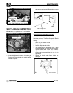
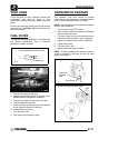
FUEL LINES
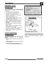
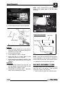
Fuel Pump
Fuel Lines
Inspect
Inspect
1. Check fuel lines for signs of wear, deterioration,
damage or leakage. Replace if necessary.
2. Be sure fuel linesare routed properly andsecured
with cable ties. CAUTION: Make sure lines are
not kinked or pinched.
3. Replace all fuel lines every two years.
NOTE: See Chapter 4 for fuel line routing diagram.


