


ELECTRICAL
10.22
Alternator Current Output Reading should be no
less than 30--40V AC above 2000 RPM on each
’leg’.
NOTE: If one or more of the stator leg output AC
voltage varies significantly from the specified value,
the stator may need to be replaced.
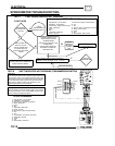
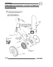
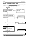
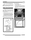
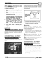
TIMING CHECK PROCEDURE
1. The ignition timing check hole is in the starter
recoil/magneto housing. Remove the check plug.
*NOTE: NOTE: The ignition timing marks are
stamped on the outside of the flywheel. Ignition timing
must be inspected with the engine at room
temperature (68°F/20° C).
2. With the transmission in neutral, start the engine
and set engine speed to 5000 ± 200 RPM.
3. Direct the timing light at the ignition timing check
hole and check the ignition timing. NOTE: Do not
allow the engine to warm up. The timing will retard
approximately 2° when the engine is warm.
If the ignition timing is not within the specified range,
adjust the stator plate position as described below.
Flywheel
Rotation
32
Timing
Pointer
30
28
EH50PL 30° BTDC @5000 RPM
Timing
Inspec-
tion
Hole
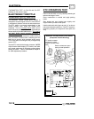
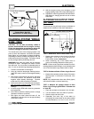
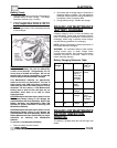
Stator Adjustment
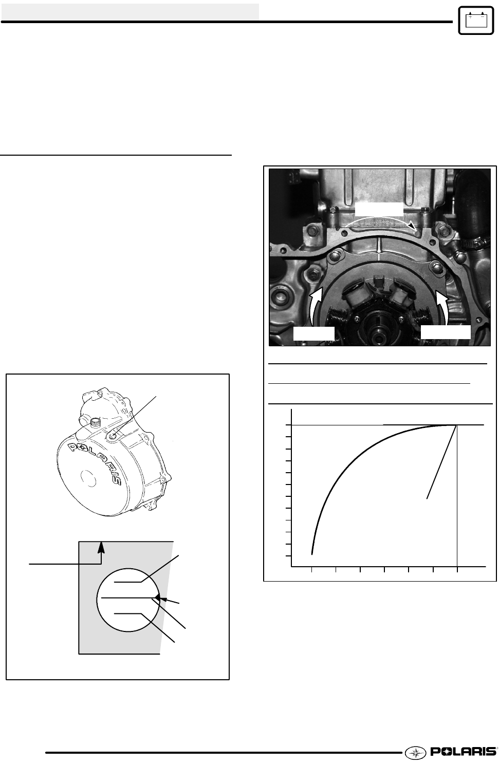
1. Remove the magneto housing.
2. Remove the flywheel.
3. Loosen the stator plate screws and adjust the
stator plate position. NOTE: Moving the stator
plate clockwise retards (delays) the ignition
timing. Moving the plate counterclockwise
advances it.
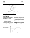
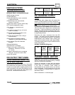
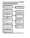
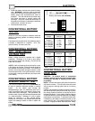
8
10
12
14
16
18
20
22
24
26
28
30
IGNITION TIMING (DEGREES) B.T.D.C.
MAXIMUMADVANCE POINT (*)
0 1000 2500 3000 3500 4000 4500 5000
TYPICAL IGNITION TIMING CURVE * ACTUAL ADVANCE POINT
MAYVARY BY SEVERALHUNDRED RPM ABOVE OR BELOW 5000
.
USE THE POINT OF MAXIMUM ADVANCE WHEN CHECKING IGNITION
TIMIN
Retard
Advance
Rotation