


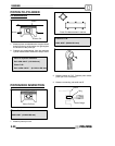
ENGINE
3.25
S If the contact area of the cutter is in the
same place, the valve guide is distorted
from improper installation and must be
replaced. Be sure the cylinder head is at
the proper temperature and replace the
guide.
S If the contact area of the initial cut is
greater than 75%, continue to cut the
seat until all pits are removed and a new
seat surface is evident. NOTE: Remove
only the amount of material
necessary to repair the seat surface.
(A)
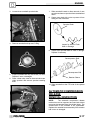
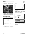
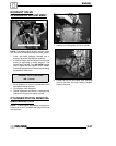
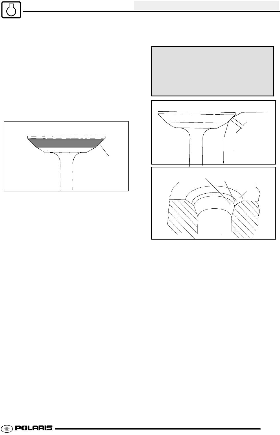
11. To check the contact area of the seat on the valve
face, applyathin coating of Prussian Bluet paste
to the valve seat. If using an interference angle
(46°) apply black permanent marker to the entire
valveface(A).
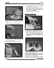
12. Insert valve into guide and tap valve lightly into
place a few times.
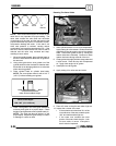
13. Remove valve and check where the Prussian
Bluet indicates seat contact on the valve face.
The valve seat should contact the middle of the
valve face or slightly above, and must be the
proper width.
S If the indicated seat contact is at the
top edge of the valve face and
contacts the margin area(B) it is too
high on the valve face. Use the 30°
cutter to lower the valve seat.
S If too low use the 60° or 75° cutter to
raise the seat. When contact area is
centered on the valve face, measure
seat width.
S If the seat is too wide or uneven, use
both top and bottom cutters to
narrow the seat.
S If the seat is too narrow, widen using
the 45° cutter and re-check contact
point on the valve face and seat width
after each cut.
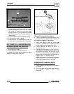
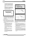
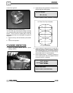
Valve Seat Width:
Intake Std: .028I (.7 mm)
Limit: .055I (1.4 mm)
Exhaust Std: .039I (1.0 mm)
Limit: .071I (1.8 mm)
Seat
Width
Bottom - 60° or 75°
Seat - 45° or 46°
Top - 30°
NOTE: When using an interference angle, the seat
contact point on the valve will be very narrow, and is
a normal condition. Look for an even and continuous
contact point on the black marker, all the way around
the valve face.
14. Clean all filings from the area with hot soapy
water, rinse, and dry with compressed air.
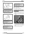
15. Lubricate the valve guides with clean engine oil,
and apply oil or water based lapping compound to
the face of the valve. Lapping is not required with
an interference angle.
16. Insert the valve into its respective guide and lap
using a lapping tool or a section of fuel line
connected to the valve stem.
17. Rotate the valve rapidly back and forth until the
cut sounds smooth. Lift the valve slightly off of the
seat, rotate 1/4 turn, and repeat the lapping
process. Do this four to five times untilthe valve is
fully seated, and repeat process for the other
valve(s).