


ELECTRICAL
10.20
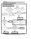
IGNITION SYSTEM
TROUBLESHOOTING
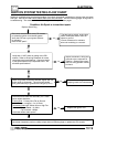
No Spark, Weak or Intermittent Spark
GSpark plug gap incorrect
GFouled spark plug
GFaulty spark plug cap or poor connection
to high tension lead
GRelated wiring loose, disconnected,
shorted, or corroded
GEngine Stop switch or ignition switch faulty
GETC switch misadjusted or faulty
GWire harness or connections wet,
corroded
GPoor ignition coil ground (e.g. coil mount
loose or corroded)
GFaulty stator (measure resistance of all
ignition related windings)
GIncorrect wiring (inspect color coding in
connectors etc)
GFaulty ignition coil winding (measure
resistance of primary and secondary)
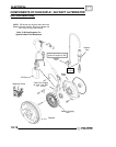
GWorn magneto (RH) end Crankshaft
bearings
GSheared flywheel key
GFlywheel loose or damaged
GTrigger coil air gap too wide (where
applicable) - should be .016-.040″
(.4-1.0 mm)
GExcessive crankshaft runout on magneto
(RH) end - should not exceed .0024″
GFaulty CDI module
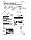
CDI OUTPUT TEST USING
PEAK READING ADAPT
OR
ORAVOLT
METER
Re-connect all CDI wires to stator wires. Disconnect
CDI module wire from ignition coil primary terminal.
Connect one meter lead to engine ground and the
other to the ignition coil primary wire leading from the
CDI module. Crank engine and check output of CDI
wire to coil. Reconnect coil wire to CDI.
Test
Connect Me-
ter Wires To:
Reading
CDI Output White/Blue to
Ground
300 Volts DC
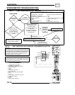
CDI CRANKING OUTPUT
TEST
The following peak voltage tests will measure the
amount of output directly from each component.
A
peak reading voltmeter can be used to perform
the
tests
. A variety of peak reading adaptors are
commercially available for use with the Fluke t 77
Digital Multimeter (PV--43568) and other digital VOMs
which will allow peak voltage tests to be performed
accurately. Follow the directions provided with the
adaptor. All measurements are indicated in DC Volts.
Readings obtained without a peak reading adaptorwill
be significantly different.
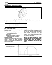
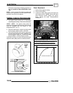
Disconnect the stator connectors from the CDI
module. Test output from the detection and pulse
(trigger) coil, and compare to the chart. The following
measurements were obtained when cranking the
engine with the electric starter, spark plug installed.
The starter system must be in good condition and the
battery fully charged.
250 Watt 4 Stroke DC/CDI Ignition
Test
Connect
Meter
Wires To:
Reading
(With
VOM)
Reading
(With Peak
Reading
Adapter)
Pulse Coil White/Red
and White
0.15 Volts
AC
4.5 Volts
DC
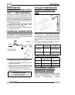
CURRENT DRAW - KEY OFF
CAUTION: Do not connect or disconnect the battery
cable or ammeter with the engine running. Damage
will occur to electrical components.
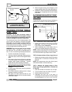
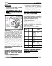
Connect an ammeter in series with the negative
battery cable. Check for current draw with the key off.
If the draw is excessive, loads should be
disconnected from the system one by one until the
draw is eliminated. Check component wiring as well
as the component for partial shorts to ground to
eliminate the draw.
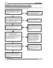
Refer to Illustration 1 on the next page.