


ELECTRICAL
10.15
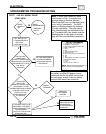
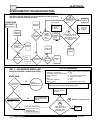
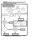
SPEEDOMETER
TROUBLESHOOTING
CONT’D
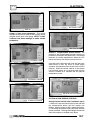
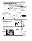
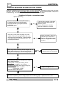
TEST 7 ---- RESET SPEEDOMETER
If thekey switch or engine stop switch is turned off with
the vehicle in motion, the speedometer indicator
needle may stick, indicating the speed at which the
vehicle was traveling when the speedometer lost
power. For example: If the ATV was traveling 30 mph
when the engine stop switch is turned off, speedomay
indicate 30 mph until reset:
1. Operate vehicle at a speed greater than indicated
on speedometer (past point where needle is stuck).
Needle should return to normal operation.
2. In the above example, the ATV speed would have
to exceed 30 mph to reset.
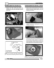
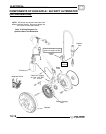
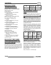
FAN MOTOR CURRENT DRAW
A current draw test will provide a good indication offan
motor condition. A worn or damaged fan motor will
draw more current, which causes a reduction in blade
speed and reduced cooling.
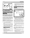
Fan Motor
Connect ammeter
to Or/Blk in series
Or/Blk
Brn
Or/Blk
1. Disconnect the harness from the fan motor.
2. Connect a DC ammeter in between the fan switch
harness wires as shown.
3. Verify fan is free to rotate. Turn ignition key and
engine stop switch to “ON” position. Read the
current draw on ammeter with fan running.
4. If the fan motor draws more than 8.8 Amps,
replace the motor.
Fan Motor Current Draw:
Less Than 8.8 Amps
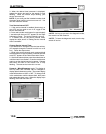
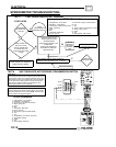
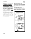
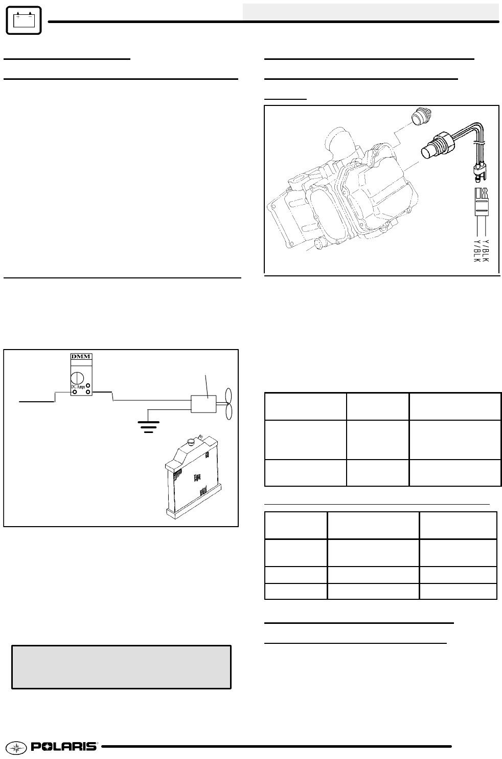
COOLANT TEMPERATURE
SENSOR (THERMIST
OR)
TEST
If thethermistor circuit is open the engineHot light and
fan will both come on. With engine cold, disconnect
lead and measure resistance of sensor between the
two Yellow/Black connector terminals. There should
be no continuity or very high resistance (see chart
below).
See “Engine Temperature Controller” on Page 10.5
for information on thermistor operation.
SITUATION
OHMS
READING
DIAGNOSIS /
ACTION
Hot light ON &
Fan ON
Above 50k Open Thermistor /
Replace Thermis-
tor
Hot light ON Below 178 Engine Overheat
or Bad Thermistor
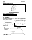
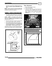
THERMISTOR READING DURING OPERATION
Condition
Approx. Reading
(Min--Max)
Temperature
Hot Light
On
178Ω -- 190Ω 215° F
(102° C)
Fan Off 296Ω -- 316Ω 180° F(82° C)
Fan On 236Ω -- 251Ω 195° F(91° C)
FAN CONTROL CIRCUIT
OPERATION /
TESTING
The fan is controlled through the ECM and thermistor.
Refer to “Engine Temperature Controller” on Page
10.5 for fan operation information. Also refer to
“COOLANT TEMPERATURE SENSOR