CHECK
SPEEDOMETER
-- KEY SWITCH ON
-- TRANSMISSION IN
NEUTRAL
--AWDSWITCHON
N
Y
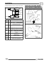
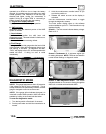
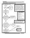
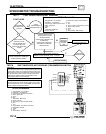
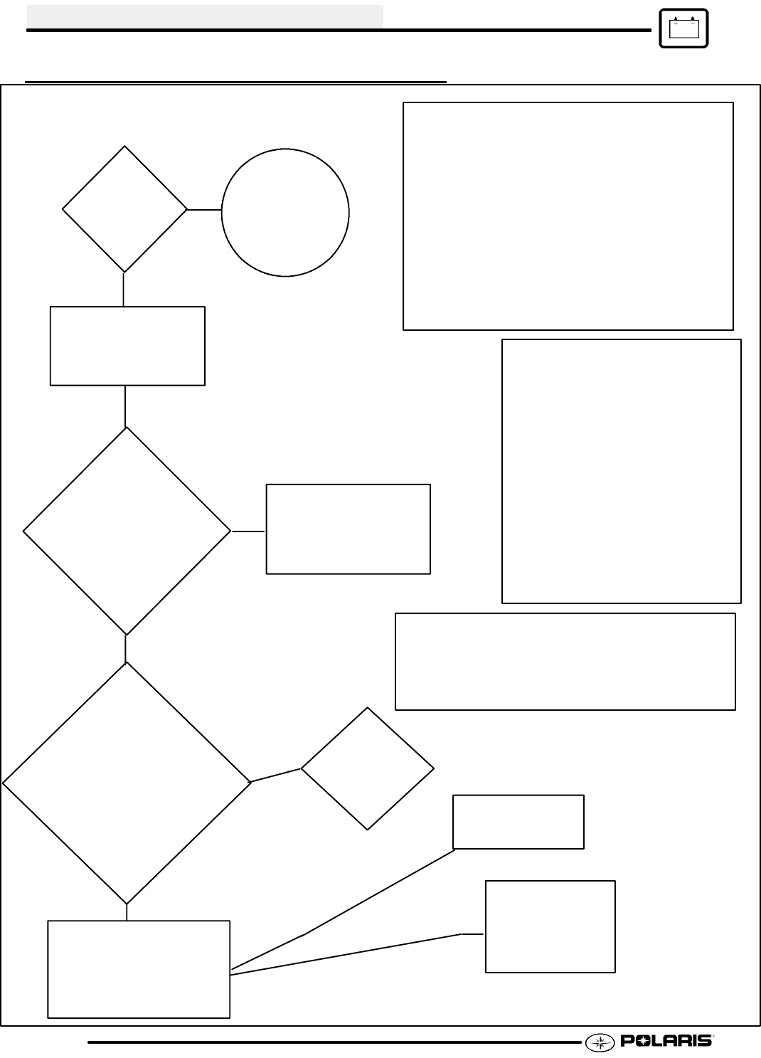
TEST 1 -- NO ALL WHEEL DRIVE
Note: If AWD icon comes on, instru-
ment cluster is O.K. Proceed to me-
chanical tests (in Service Manual).
Check the AWD icon on instrument clus-
ter to verify it’s operation. The AWD
switch is directly powered by switched
12 volts (red/white). The gear switch
only interfaces with the instrument clus-
ter. To enable AWD, the cluster must be
displaying low or high gear, or reverse
gear with the override button pushed in.
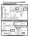
(PERFORM
TEST 2)
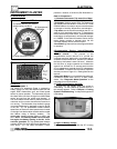
SPEED
READOUT
OK?
START HERE
ON HUB COIL
CONNECTOR
(LEAVE IT CONNECTED)
MEASURE FOR 12V FROM
BROWN/WHITE TO THE
COIL BODY
(GROUND)
NOT AN INSTRUMENT
CLUSTER PROBLEM;
CHECK AWD SWITCH
AND WIRING
N
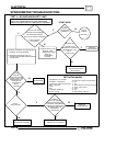
LEAVE AWD
DISCONNECT 16 PIN
CONNECTOR FROM CLUSTER
CHECK FOR 12V
FROM BRN/WHITE
TO GROUND
Y
Y
SWITCH ON
RECONNECT CLUSTER
LEAVE HEADLIGHT POD
DISASSEMBLED
SHIFT TO LOW OR HIGH
LEAVE AWD ON
Y
Y
REPLACE
INSTRUMENT
CLUSTER
PROCEED TO
IF AWD PROBLEM
PERSISTS.
MECHANICAL AWD
COMPONENTS
N
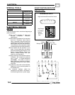
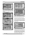
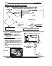
1. Orange/White-- 12V Constant
2. Red/White-- 12V Switched
3. Grey/Orange-- Mode/Override button
4. Black-- Ignition Kill
5. Green
6. Blue
7. Yellow/Red-- RPM Input
8. Brown-- Ground
9. Blue White-- Engine Overheat Switch
10. N/C
11. N/C
12. Purple/White-- Fuel Sender (not used)
13. Brown/Red-- Neutral
14. White
15. N/C
16. Brown/White-- AWD Coil
16 Pin Connector
WIRING
PROBLEM
N
TURN KEY SWITCH OFF
TURN KEY SWITCH ON
TURN KEY SWITCH OFF
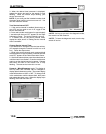
Note: Reversing polarity when connecting
the battery or other DC power source
backwards will fail the AWD control and
the instrument cluster If the key switch
and the AWD switch are turned on.
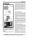
NOTE: Refer to the wiring schematic in
back of book for more information.
ELECTRICAL
10.10
SPEEDOMETER TROUBLESHOOTING


