


BODY / STEERING / SUSPENSION
5.2
TORQUE SPECIFICATIONS
COMPONENT FT. LBS.
(IN.LBS.)
NM
Front Wheel Nuts 27 37
Front Hub Nut 70 95
Front A-Arm Attaching Bolt 30 41
Front A-Arm Ball Joint Stud
Nut
25 35
Handlebar Adjuster Block 11--13 15--18
Master Cylinder Clamp
Bolts
(45-55) 5.2-6.3
Rear Shock Bolt (Upper) 30 41
Rear Shock Bolt (Lower) 30 41
Rear Wheel Hub Nut 80 108
Rear Wheel Nuts 27 37
Upper Stabilizer Support
Nuts
17 27
Upper Control Arm Mount-
ing Bolt
35 48
Lower Wheel Bearing Carri-
er Bolt
30 41
Strut Rod Retaining Nut
(Top)
15 21
Strut Casting Pinch Bolt 15 21
TieRodEndJamNut 12-14 17-19
TieRodEndCastleNut 40--45 54--61
TieRodEndAttachingBolt 25-30 35--41
NOTE: Refer to exploded views throughout this
chapter for identification and location of components.
SPECIAL TOOLS
PART NUMBER TOOL DESCRIPTION
2870871 Ball Joint Replacement Tool
2870872 Shock Spanner Wrench
2870623 Shock Absorber Spring
Compression Tool
2871572 Strut Rod Wrench
2871573 LH Strut Spring Compressor
2871574 RH Strut Spring Compressor
7052069 Charging Needle
2200421 Gas Shock Recharging Kit
2871352 Shock Rod Holding Tool
2871199 Seal Sleeve Installation Tool
Kit
2870872 Shock Spanner Wrench
2871351 Foxt Shock IFP Depth Tool
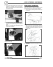
PLASTIC INSERT REMOVAL /
INSTALLA
TION
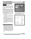
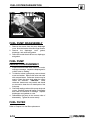
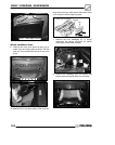
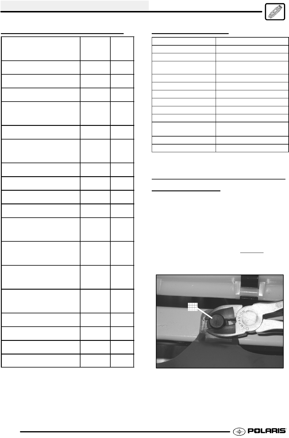
Some Polaris ATVs use a two piece plastic insert in
place of a metal screw. The plastic inserts are easy
to remove and install.
1. Use a a pair of diagonal side cutters to lift the
plastic insert (A) until you feel some slight
pressure or lift the insert approximately 1/4” (6.35
mm). Apply just enough pressure on the side
cutters to lift up on the insert. DO NOT
apply too
much pressure on the side cutters, or damage to
the insert will occur.
A