


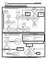
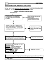
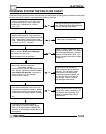
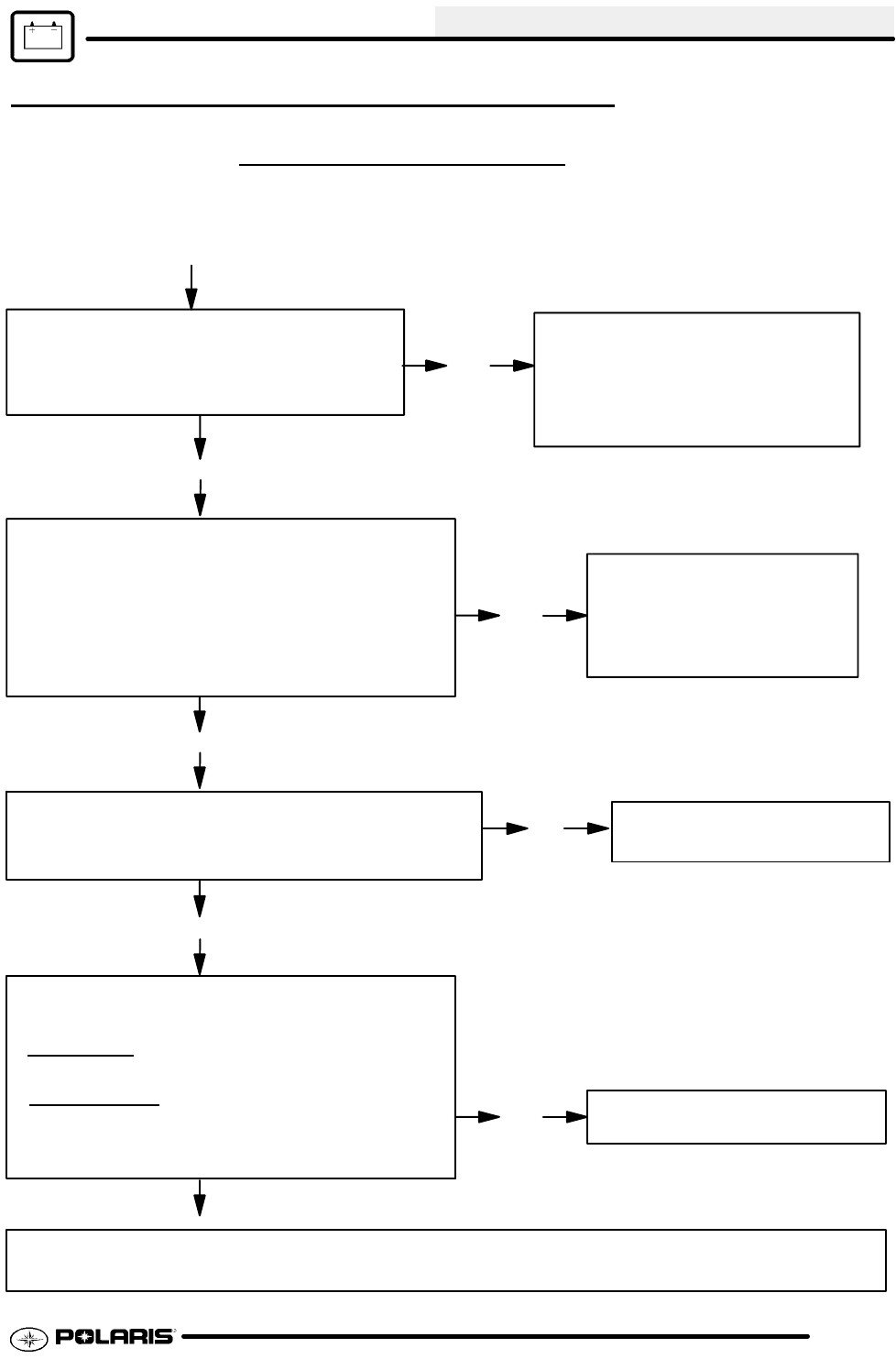
Condition: No Spark or intermittent spark
Disconnect the black wire at the CDI module
to isolate the ignition from the kill system.
Verify the CDI has a good ground (Brown)
for operation.
Does it have spark?
-Test the ignition switch, engine stop
switch, and speed limiter circuit for
shorts to ground.
-Check connectors for moisture,
wire color matching or corrosion.
Inspect connectors, wiring and
grounds to the component in
question. Replace the compo-
nent if a wiring problem cannot
be found.
Yes
No
Yes
Yes
No
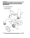
Check coil ground connection between engine and coil
mount using an ohmmeter. The coil mount should
have good continuity to ground on the engine (0-.2 Ω).
Replace Spark Plug
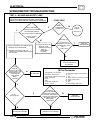
Disconnect and check the secondary coil. Resis-
tance values should be:
Primary Side
- Primary Wire Tab to Ground
(on coil mount or engine): .3 to .5 Ohms
Secondary Side
High Tension Wire to High Ten-
sion Wire-- Cap installed - 10,500Ω
Cap removed - 6300Ω
Are these values within specs?
Replace the ignition coil.
No
Yes
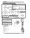
If all of the above tests are within specifications, and all grounds, connections, and wire color coding
have been inspected, perform voltage output tests on following page or replace the CDI module.
Clean coil mounting area.
Repair ground wire connections.
No
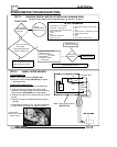
Verify that 12 VDC power is getting to the CDI
module. Refer to the wiring schematic for meter
connections and specifications. Compare results
to the specifications on the exploded views. Are
all within specifications?
ELECTRICAL
10.19
IGNITION SYSTEM TESTING FLOW CHART
Whenever troubleshooting an electrical problem, first check all terminal connections to be sure they are clean
and tight. Also be sure that colors match when wires are connected
. Use the following pages as a guide for
troubleshooting. The resistance values are also given on the specification pages.