


Reference Manual
00809-0100-4832, Rev AA
October 2004
5-3
Rosemount 3095FC
RESETTING THE 3095FC If problems occur that appear to be software related, try resetting with a Warm
Start, Cold Start, or Jumper Reset.
Warm Start The re-initialization is performed by setting a parameter in the Rosemount
User Interface Software Flags. The re-initialization includes the Tasks,
Database, Communication Ports, sensor module, and I/O. It does not change
the current configuration of any parameters.
1. Log into the Rosemount User Interface Software.
2. Connect the PC to the 3095FC.
3. Perform “Backup Configuration Information” on page 5-1.
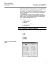
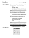
4. Select 3095FC > Flags
5. Click on Warm Start
6. Apply to save the change.
Cold Start The re-initialization is performed by setting a parameter in the Rosemount
User Interface Software Flags, called Cold Start. The re-initialization includes
the Tasks, Database, Communication Ports, Sensor, I/O, and restoring the
saved configuration, if there is one. It also includes resetting or clearing other
items, based upon the selection made in the Options screen.
1. Log into the Rosemount User Interface Software.
2. Connect the PC to the 3095FC.
3. Perform “Backup Configuration Information” on page 5-1.
4. Select 3095FC > Flags.
5. Click on Cold Start.
6. Apply to save the change.
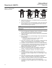
Jumper Reset The Reset jumper located on the LCD (if installed) or on the Battery Charger
Board can be used to perform a special type of cold start. The jumper permits
a power-up reset to re-establish a known operating point. It includes
re-initializing the Communication Ports to the factory default configuration.
The cold start does not include any of the clearing options available in a Cold
Start performed using Rosemount User Interface Software.
NOTE:
This type of reset restores the communications ports to the factory
configuration defaults. Some user-entered configuration parameters may be
lost. Therefore, back up any required data before performing the reset.
1. Perform “Backup Configuration Information” on page 5-1.
2. Unscrew the front end cap cover (LCD end).
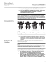
3. Place the reset jumper (located on the LCD if installed or on the
Battery Charger Board at J2) in the Reset position.
4. Cycle the power.
5. Remove the reset jumper and install it in the normal (NORM) position.
6. Replace the front end cap cover (LCD end).
7. Perform the “After Installing Components” on page 5-4.
The reset procedure loads the factory default values into the communication
ports.