


Reference Manual
00809-0100-4832, Rev AA
October 2004
Rosemount 3095FC
3-48
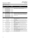
Register numbers should be unique for a given communication port.
Registers may be duplicated as long as they are assigned to separate port or
located in a separate Modbus configuration table. If a register number is
duplicated within the same Modbus function table, the first occurrence is
used. In addition, it is best to number the table from the smallest register
number to the largest register number, especially when using two table entries
to configure a continuous group of registers. Up to fifteen different lines can
be configured for Modbus Functions 4 and 16. Up to thirty different lines can
be configured for Modbus Function 3, split into tables 3A and 3B. By making
the registers continuous, meaning the Starting Register address of a new line
is one greater than the Ending Register address of the previous line, a
continuous data table can be created up for Modbus Function 3, 4, or 16 up to
the limit of 240 bytes. This type of data table allows access to all its data with
one request.
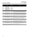
Up to fifteen different lines can also be configured for Modbus Function Codes
1, 2, 5, 6, and 15. For Function Codes 1, 2, 5, and 15, the parameter specified
should be a single-byte parameter type, preferably a status parameter (only
bit 0 is used), because this function packs the data into a binary format for
transmission. Each address span must be unique within the function for
proper operation. If not, the first valid address is used.
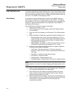
Modbus Register tables allow the user to map Modbus Registers to 3095FC
Point Type, Logical, and Parameter (TLP) numbers. One line in the Modbus
Register table can be used to map more than one register-TLP pair by using
either Point Indexing or Parameter Indexing.
Point Indexing means that the Start Register is mapped to the selected TLP.
Subsequent registers, through the End Register, are mapped to the same
point type and parameter and increment as the point logical number.
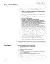
Parameter Indexing means that the Start Register is mapped to the selected
TLP. Subsequent registered, through the End Register, are mapped to the
same point type and point logical number, and increment the parameter
number.
Once a register is mapped, it can be referenced by any Modbus request,
providing the data type of the TLP is appropriate for the Function Code. If the
native 3095FC data type does not me the requirements of the Modbus host
device, conversion codes are available to convert data to the required data
type. The user can select to have the mapping apply to all 3095FC
communication ports or on a selected port only.
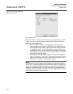
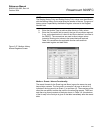
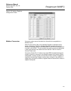
Use the following steps to Configure the Modbus Registers.
See Figure 3-28 on page 3-51.
1. Select Configure > Modbus > Modbus Registers. (See Table 3-7 on
page 3-49).
2. Select the Function Index to which the maps are to be registered.
There are 9 function indexes available, each corresponding to a
Function Code displayed in the Function name field. Refer to Table
3-2 on page 3-38 for a detailed description of supported Modbus
Function Codes.
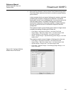
3. Enter a Function Name up to 20 characters to distinguish between
the different Modbus Register tables.