


Reference Manual
00809-0100-4832, Rev AA
October 2004
Rosemount 3095FC
2-8
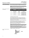
Table 2-6. Communications
Card Signals
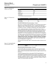
Table 2-7. EIA-232 (RS-232)
Communications Card Wiring
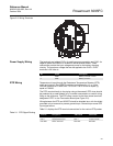
Ground the Transmitter Grounding reduces the effects of electrical noise on the unit's operation and
protects against lightening. The 3095FC provides lightening protection for
built-in field wiring inputs and outputs. Install a surge protection device on the
DC voltage source system to protect the device against lightning and power
surges.
The 3095FC has two grounding screws inside the enclosure. It is
recommended that a minimum of 14 AWG wire be used for the ground wiring.
To minimize signal errors caused by EMI (electromagnetic interference), RFI
(radio frequency interference), and transients, The I/O signal wiring cable
should be an insulated, shielded, twisted-pair. All grounds should terminate at
a single point.
NOTE
Grounding wiring requirements for DC voltage sources equipment are
governed by the National Electrical Code (NEC). When the equipment uses
DC voltage sources, the grounding system must terminate at the service
disconnect. All equipment grounding conductors must provide an
uninterrupted electrical path to the service disconnect.
Earth Grounds
All earth grounds must have an earth to ground rod or grid impedance of 25
ohms or less as measured with a ground system tester. The grounding
conductor should have a resistance of 1 ohm or less between the 3095FC
enclosure ground and the earth ground rod or grid.
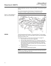
Pipelines With Cathodic Protection
The 3095FC must be electrically isolated from the pipeline. Electrical isolation
can be accomplished by using insulating flanges upstream and downstream
on the meter run. In this case, the Rosemount 3095FC could be flange
mounted or saddle-clamp mounted directly on the meter run and grounded
with a ground rod or grid system (see “Earth Grounds” on page 2-8).
Signals Action
RTS The request to send signals that the modem is ready to transmit.
RX The RXD receive data signals that data is being received at the
communications card.
TX The TXD transmit data signals that data is being transmitted from
the communications card.
Signal Label
Signal Common Negative COM
(1)
(1) GND at Pin 1 and Pin 3 are identical. They are separated for ease of wiring.
Switched Power TX
(2)
+ B
(2) Switched Power is used with an internal radio or cell phone. It does not power external devices.
Ground COM
(1)
Request to Send RTS
Tip / Receive Data RX
Ring / Transmit Data TX
(3)
(3) Transmit (TX) connects to the 3095FC unit's receive.