


Reference Manual
00809-0100-4832, Rev AA
October 2004
3-23
Rosemount 3095FC
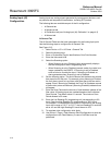
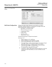
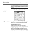
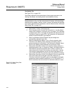
Figure 3-16. Opcode Table
Screen
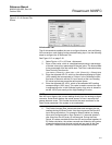
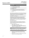
Radio Power Control
Configuration
Radio Power Control conserves battery power to a radio or any other
communicating device. Radio power is controlled either by the DTR signal or
by a Discrete Output (DO). Because there are separate Radio Control points
for COM1 and COM2, radio power cycling for COM1 can be configured
differently from that for COM2, including independent timer values and
separate output controls using the Output Definitions options.
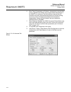
For each Radio Power Control point, the power cycling can be configured to
automatically change three times a day. During each of these three periods
(Zone 1, Zone 2, and Zone 3), the ON and OFF times can be setup to operate
at various intervals. Figure 3-17 is a graphical depiction of how the power
control operates within each time “zone.”
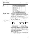
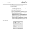
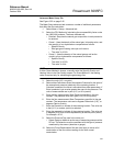
Figure 3-17. Radio Power
Control Timing
If communications occur during the ON time, the time is extended by the Hold
Time. The DO remains ON and receives interrupts remain enabled for the
duration of the Hold Time. When the Radio Power Control parameter is
Enabled, radio power cycling is activated. The Low Battery Shutoff parameter
allows power cycling to be automatically disabled whenever the input voltage
to the 3095FC falls below the specified threshold.
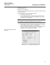
See Figure 3-18 on page 3-25.
1. Select Configure > Control > Radio Power Control.
2. Select the Radio Power Control point to be configured. Enter the Tag
(10-character) to identify this point.
During the ON time:
• The DO is switched to ON.
• Communication may occur.
During the OFF time:
• The DO is set to OFF.
• Communication does not occur.
Time = N
Time = N
Off Time
On Time Hold TimeOn Time Off Time On Time
Host Communication Detected
Zone 1
Zone 2
Zone 3